

Description
I built a serial proxy to solve the communication issues preventing the mill to work with modern computers. An Arduino mini is used to translate a 19200 serial connection using XON/XOFF (software flow control) to a 9600 CTS (hardware flow control) accepted by the mill.

Features
- Arduino mini used as serial proxy between the PC and the mill.
- Translates 19200 software flow control to 9600 hardware flow control.
- Solves all communication and driver issues that rendered the mill useless.
- Powered by the USB to serial adapter
Development
The Roland MDX mill is a great hobby CNC mill perfect for milling PCBs and small prototypes. I have previously upgraded the mill by adding USB connection instead of the serial interface. It worked with special drivers on previous Windows installations but on Windows 10 it’s impossible to get it up and running. After some debugging, I realized that the timing of the hardware flow control is the critical problem where modern computers and USB2serial adapters are simply too fast for the mill. Another problem is that hardware flow control (CTS/DTS) is not available on most USB to serial adapters.
I considered replacing the printers control card, to directly communicate with the motors using a modern 3d printer controller, but then I would have to rewrite the hole infrastructure of programs that I am using for the mill. When I realized that this was a dead end, I spent way too much time trying to connect the mill to different versions of Raspberry pies with hardware flow control available (this was when I realized that the timing is the problem and the pi is also too fast for the printer).

Instead I solved the problem in a much easier way – using an Arduino as a serial proxy translating the communication between the PC and the printer, bit banging the hardware flow control in a speed that the printer accepts. With this approach I could also use software flow control to the PC. A small buffer is used to avoid timing issues and since the software flow control uses some extra bytes, I increased the baud rate to the PC.
Since I already had a USB to serial adapter in the mill, I used an Arduino mini (5v version). The Arduino nano would have been used otherwise since it has the USB to serial interface integrated.

After the fix, I have used the mill to create PCBs. I used my html based post processor and the resulting files was sent to the mill using putty, configured for software flow control and 19200 baud rate. It works like a charm!

Program
The Arduino program is quite simple, the serial buffer is monitored and allows more data from the PC (XON) when it contains less than 8 bytes. When the buffer reaches 16 bytes XOFF is sent to pause communication. On the mill side byte by byte is transferred to a soft serial port and the hardware flow control CTS signal is monitored to control the communication.
One LED indicates data in buffer and one LED indicates that the mill has halted communication using CTS.
None of my programs on the PC listens to the mill, so the software RX port is not used (but could easily be added if needed).
I also added optional switches that can transfer pre-recorded commands to the mill. This is great for calibration, where different keys can be used to move the mill to 0,0,0 or 1,1,0 without using the PC.
Assembly
Since I already had the USB to serial adapter in place, I simply cut the wires and added the Arduino mini in between. In this post you can find how to connect the serial interface directly to the mill (you need to lift the TX pin on the DS14C238 IC and connect directly to the pad)

- VCC is connected to VCC on the serial adapter (powered by the USB cable)
- GND is connected to both the serial adapter and the mill.
- Pin 0 – RXD is connected to the serial adapter to the PC
- Pin 1 – TXD is connected to the serial adapter to the PC
- Pin 10 – RX can be connected to the mill, but is not used in the software.
- Pin 11 – TX is connected to the mill.
- Pin 2 – CTS is connected to the mill CTS
- Pin 12 is connected to a LED in series with a 1k resistor to GND
- Pin 13 is already connected to the on-board LED on the mini.
- Pin 3-7 can be connected to switches to GND for pre-recorded commands (optional)
- DTR is connected to the serial adapter to allow Arduino programming from the Arduino development tools without the need for a special adapter.
Bill of Materials (BOM)
- 1x Arduino mini
- 1x USB to serial adapter
- Some wires
- 5x switches (optional)
Licensing

It is the problem I have, I had my roland mdx 15 saved, I decided to use it, and with windows 10 nothing, consult, if I install windows xp? Is the issue solved, or would it work for modern hardware? Thank you for sharing the information.
Hi
Unfortunately, I can’t say if win xp will work or not. I suspect it is a combination of legacy drivers and timing of hardware interfaces. The best way is to try – if it doesn’t work the serial proxy should work (but i have only tested it with my own CAM tools, tx, no rx)
Hi Johan,
Do you still own the mill?
I have an MDX-15 but don’t have spindle motor for it, I also can’t find any good techincal information for the motor.
I was wondering if you’d be so kind as to take the cover off the motor and record the pin out for the DIN-Mini connector to the motor?
That way I can wire up my own motor.
Thanks.
Hi Jack. I still have it, but it is located at my summerhouse (that is now closed for the winter)
If I go there, I will take a photo of the spindle motor and try to record the pinout.
You can probably find the correct pin by measuring the wires to the PCB. The driver circuit should stand out and most of the pins are probably for powering the sensor accessory.
Hi
I went to our summerhouse today and was able to bring the motor back home :)
Holding the Cable and looking at the connector shows eight pins inside the round metal case:
1 2 3
4 5 6
7 8
The motor is connected to 2 and 3 and the ground is connected to the metal case and the metal frame of the spindle.
The motor is marked:
SAGAMIMICRO
2838N 12
Thanks for the information.
I have managed to connect a new motor with similar ratings. I can get the motor to start by jogging the Z-axis down.
Though when the motor stops, all the lights start flashing. According to the manual, this indicates the motor cable has detached.
I suspect the original motor has a capacitor or kickback diode attached to the motor contacts. The new motor I have doesn’t have anything, this way the circuit does not detect the motor correctly and shuts down.
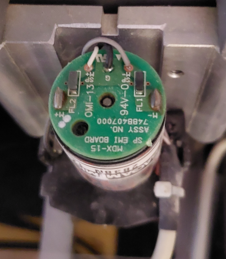
Did you happen to see any caps/didoes under the hood of the motor by chance?
Sorry for the hassle, you seem to be the only person actively discussing this machine.
Hi, you are right. There are two SMD diodes named FL1 & FL2, in series between the motor and the M+ / M- cable. Test and see if it helps.
Hi, I have a MDX20 and an MDX15 Modela. I have purchased an FDTI USB to serial converter but the model’s do strange stuff. I suspect it is the buffer issue that you talk about that is causing the issue. Is there a way of using the arduino fix externally, ie still use the port on the back of the machine? I am no that confident soldering to the PCB.
I have not tested it, but is should be possible to place it on the outside if you convert ttl to rs232 levels.
You have two options:
(pc with usb) -> (usb to ttl adapter) -> (Arduino mini proxy) -> (ttl to rs232 adapter) -> (mdx mill)
(pc with usb) -> (Arduino nano proxy) -> (ttl to rs232 adapter) -> (mdx mill)
The option with the nano requires minor modification of the code to use the built in usb2serial interface.
It should be possible to power everything from 5V USB if the ttl-232 converter has built in charge pump.
Double check that the ttl-232 converter supports rts cts signaling…
Let me know if it works!