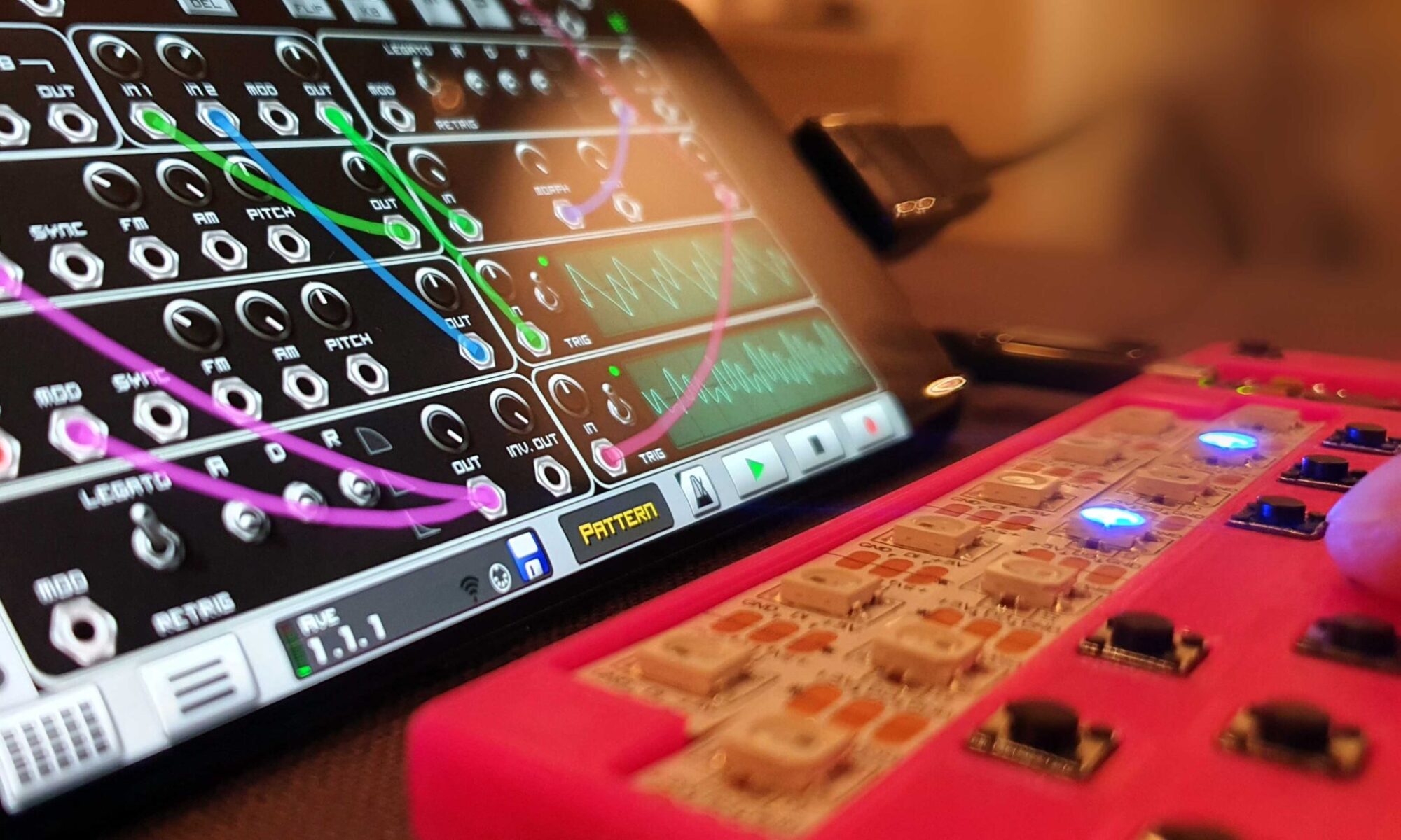
3D printed USB-C Eurorack power supply

Build your own USB powered Eurorack PSU

For the versatile LEET modular project, I designed a 3HP power supply that converts 5V USB-C to +12V and -12V. It is convenient to use, but not suited for powering a large number of units.

It should be quite straight forward to build it on a stripboard if you don’t have access to a 3D printer.

The 3D printed 3HP case

Specification

  • Easy to build – only five components
  • No need for a custom PCB
  • Small formfactor (3HP)
  • Power it from your computer or power bank.
  • Suitable for small loads (5-6 LEET modules when powered from USB)
All components but the pin header…

BOM

  • USB-C breakout PCB
  • CN6009 Step up DC/DC module
  • MP1584 Step down DC/DC module
  • Small slide switch (~20x6x13 mm)
  • 2×5 pin header
  • PLA for the 3D printer

Build

Download the 3D models and print them. I used the following parameters:

  • PLA material
  • 0.4mm nozzle
  • Support for the main body

The assembly is quite straight forward, but the limited space makes it a bit challenging. I recommend that you connect everything outside the case, with wires in suitable length and then trim the voltages (+/-12V). When everything works – move it in place and resolder wires when necessary.

a step down module creates -12V from a virtual ground

Test the unit carefully before you connect it to other modules. It works great for me, but build and use it on your own risk – I do not take any responsibility for damage caused by this project.

Download project files

All files required for this project are available at this GitHub repository:

https://github.com/vonkonow/LEET-Modular/tree/main/power

License

This project is open source under MIT License
(Attribution is optional, but appreciated /Johan von Konow ;)

Cardiac – Recreating an educational paper computer from 1968

Photo of assembled CARDIAC

Description

CARDIAC (CARDboard Illustrative Aid to Computation) is a learning aid to understand how a computer operates, created more than 50 years ago by David Hagelbarger and Saul Fingerman for Bell Labs. Building it is easy and can either be done by hand, or with a CNC knife if you have access to one (this saves time and gives an outstanding result).

Features

  • Anyone can build it with just a printer, paper and scissors or a cutting knife!
  • 3 sheets of paper
  • 10 instructions
  • 100 memory cells (using a pencil)
  • High resolution vectorized graphics
  • Original colour scheme
  • Cutting files for CNC knife available
  • Learn how a computer really works and how a program is executed.

Development

I wanted to build a CARDIAC myself but was disappointed in the quality of the black and white scans available. There are high resolution recreated versions, but the ones I found lacked the beautiful aesthetics of the original. Recreating a good looking vectorized version seemed like a great challenge that could hopefully be used by others besides me.

Instead of outlining existing scans I recreated everything from scratch. This allowed me to fit the design on three pieces of A4 or letter paper, while maximizing the computer size (memory and CPU are on separate sheets). If you look closely you will notice that the slides are reversed from the original, since this felt more natural to me. After creating all slides and panels in cad (Rhino3d), I did a few iterations with printed samples. Once everything was working properly, I switched program to Illustrator to finetune the graphics, using similar colours and fonts as the original. I added bleed for the cutting and even spent energy on recreating the ladybug graphic and vectorizing the original ell logo from that time.

The artwork is available in two versions, one with lines for manual cutting and one without lines for CNC cutting. The CNC version has pass-marks to auto align the printed graphics with the cutting path (tested on a silhouette cameo and A4 paper)

Image of page 1 (for manual cutting). Download high resolution PDF below.

Programming the CARDIAC

The original scanned manual explains in a good way how the computer works and describes everything from input devices (punch cards) to output devices (high speed printers). It’s a fascinating read that explains how a computer worked 50 years ago, and even though a lot has changed, the basics of a program is still the same.

Manual: https://archive.org/details/CardiacCardboardIllustrativeAidToComputation

To better understand the computer, I wrote a small program that is included in the artwork. Running this program is a good start for all users. Can you figure out what it does?

Before using the cardiac I only had a vague understanding of what bootstrapping a computer really meant. After writing my first program the brilliance of the concept is now clearer than ever (luckily computers don’t get bored…)

Assembly

Building the computer is very easy, just print, cut and put the slides together. I added numbers to avoid placing them in the wrong order. If you cut it by hand, I recommend that you skip cutting the round holes for the program (sheet 2), since this is a tedious task and you can easily replace moving the bug between holes with moving a small stone or mark current position with a pencil and eraser.

If you build it and appreciate the work, I would be happy if you shared your experience in the comments below. You can also share your programs to allow other to use them

Bill of Materials (BOM)

  • 3x sheets of A4 paper (preferably a bit thicker ~120g/m2)
  • 1x printer (preferably colour laser)
  • 1x cutting knife or 1x computer controlled knife (I used Silhouette Cameo)

Documents

Licensing

This work is licensed under a Creative Commons Attribution-NonCommercial-ShareAlike 4.0 International License.

Repairing noise canceling Bose headphones

Description

Repair guide for broken noise canceling Bose QC25 headphones

Features

  • 10 minutes fix
  • Bad design and even worse support from Bose
  • Works like new after simple fix

Development

My wife has a pair of Bose QuietComfort 25 which she mainly uses during flights. After three years of rare usage, the right speaker started to fail. A search on the web showed that this was far from an isolated case, as tons of people had experienced the identical error. Unfortunately, Bose was not very service-minded and even after explaining that this was a design error, they still refused to repair the headphones without a fee that was close to buying a new pair. The whole experience was very unprofessional, and I assure that we will think twice before ever buying any Bose products again…

Not having much to lose, I decided to see if they could be fixed. Taking them apart was rather easy using the following steps:

  1. Remove the ear padding (just pull).
  2. Remove the R and L cloth inside the earpieces (secured with adhesive).
  3. Unscrew two screws using a Philips 00 screwdriver.
  4. Remove the metal grid on the outside of the earpiece, exposing the PCB with wire connections.

Since the sound worked in some positions, but was lost when folding the headphones, I suspected that there was a breakage in the cable. Taking apart the linkage mechanism and headrest didn’t help much, since all signal wires used enameled copper wire, I realized it would be difficult to replace the broken one. I tried to locate the error with a multimeter, looking for a breakage and/or shortage. Intermittent errors are sometimes difficult to find, and when I noticed that there were three ground wires, I simply de-soldered one of them in both ends and added the GND-wire in parallel with the faulty signal wire.

Photo of the PCB of the headphones, before the signal wire was isolated completely.

However, this didn’t solve the problem, but at least it ruled out the breakage error and indicated a shortage, probably due to worn out enameled insulation. I de-soldered the faulty signal wire and insulated both ends with shrink tubing. The ground wire was soldered as replacement to the signal pads on the PCBs. This solved the issue and I put everything back again using above steps in reverse order.

I was worried that removing one of the three ground wires could cause some interference, but there were no added noise and the headphones operates as new.

Summary:

I’m disappointed in BOSEs poor support and lousy design with thin enameled insulation that wore out after sparse usage, but I’m glad that the problem was easy to fix…

Bill of Materials (BOM)

  • 1x broken noise canceling headphones
  • 1x Philips 00 screwdriver

Licensing

This work is licensed under a Creative Commons Attribution-NonCommercial-ShareAlike 4.0 International License.


PokeBot – Catch Pokémon’s in your sleep (and at work)


Another robot stealing our jobs...

Description

Pokémon GO catching robot using a modified Pokémon GO plus controlled by an Arduino to automate Pokémon catching and PokeStop spinning.

Features

  • Graphic display for statistics (Low-cost Nokia 5110)
  • Configurable target of balls and PokeStop spins
  • Random delays prevent Niantic to detect the hack
  • Detachable 8pin connector (Pokémon GO plus can still be used standalone)
  • Fully customizable code (built in Arduino environment)

Development

The ongoing legendary Pokémon raids often results in a large amount of Pokémon’s needing revives and potions. I wanted to automate the monotonous task of spinning stops in Pokémon GO. There are endless ways to cheat, but most of them can be detected by Niantic, possibly resulting in banning your account. Inspired by the simple vibrator hack (wiring the vibrator of Pokémon GO plus to the pushbutton) I decided to develop a more advanced version (read overkill). By connecting each color of the RGB led, the vibrator and pushbutton to a small connector, I can hook it up to a microprocessor to detect if the mobile phone has found a PokeStop or a Pokémon. Even the number of items from a PokeStop can be read from these signals. By using random waiting times, it is very difficult to differentiate the PokeBot from a physical player.

The best feature with Pokémon GO is that the kids (read you) are active and outdoors instead of sitting still indoors. Therefore, I see this hack as a complement. PokeBot will fill up your inventory with Poké Balls after a good day’s hunt.  Please note that Pokémon GO plus will only throw red balls, so if you want to catch great Pokémon’s you still have to spend some AFK time…

Modifying the Pokémon GO Plus


The special screws can be removed with a small flat screwdriver
Pokemon GO Plus taken apart. (Top middle shows removed parts)


This is the most challenging part, requiring tiny tools, SMD soldering and basic plastic modification skills. I started by taking the Pokémon GO plus (PoGoP) apart. There are three tiny custom screws, but they can be unscrewed with a miniature flat screwdriver and some force… I removed the PCB and soldered enameled wire to the following pins:

  1. RGB Red
  2. RGB Blue
  3. RGB Green
  4. Vibrator
  5. Push button
  6. VBATT (3V VCC)
  7. GND


The enameled wire is soldered directly to the components.

Note that the positive vibrator wire is removed from the PCB, disabling it until you connect it to VBATT. The seven wires were then trimmed and soldered to a female 2×4 pin header. The eight position were filled with epoxy, avoiding the male connector to be inserted upside down. I had to cut away the tip of the black housing and remove the bottom screw to integrate the pin header nicely inside the PoGoP. I also needed to trim some plastic ribs to fit the inner part of the pins. This can be done with a Dremel, but I used a wire cutter and a breakaway knife to get more precision. Once everything is fitting prefect, I measured the signals and glued the pin head to the housing with 2k epoxy.

Since the bottom screw was removed I simply placed a piece of double sided adhesive in the battery lid to secure it to the housing.

Standalone operation


Standalone operation with small wire to enable vibration

Since all the signals are connected to a pin header the PoGoP can easily be detached from the PokeBot and used as intended for Pokémon walks. To enable the vibrator, I used a bent pin from a pin header to bridge the vibrator signal to VCC. Removing the pin enables standalone “quiet” operation, only signaling status thru LEDs (perfect for boring meetings ;)

Building the microcomputer

The microcomputer is easily built by connecting the Pokémon GO pin header, LCD and switches to the Arduino. Please note that both the Pokémon GO and LCD requires 3V signals, while the Arduino I used has 5V signals. Instead of using level converters I simply connected 1k resistors in series, reducing the current and protecting the devices. I soldered the wires directly to pin headers and added some heat glue to secure everything once I had verified the function. You can use breadboard wires if you want a quicker (but less permanent connection)

Arduino Pinout

0          NC (Not Connected)
1          NC
2          Switch 1
3          Switch 2
4          NC
5          1k to LCD D/C
6          1k to LCD RST
7          1k to LCD SCE
8          NC
9          LCD backlight (my LCD module have built in serial resistors)
10         NC
11         1k to LCD DN (MOSI)
12         NC
13         1k to LCD SCLK

A0         to 1k to PoGoP Pin Header Vibrator
A1         1k to PoGoP Pin Header Switch
A2         1k to PoGoP Pin Header Blue
A3         1k to PoGoP Pin Header Red
A4         1k to PoGoP Pin Header Green
A5         NC

3.3V       LCD VCC & PoGoP VCC
GND        LCD GND, PoGoP GND & config Switches

The program

The program is quite simple; I used the LCD functions library for the Nokia 5110 display and initialized the pinouts according to their functions (enabled weak pullups for vibrator, RGB led and the config switches).

Subroutines were created to handle repetitive commands as display updates, keypress and random waiting times. Note that the display updates also echo the info on serial, allowing information and debugging on a PC terminal. This also allows you to skip the display and run in standalone if needed.

I played around with the graphical display functions and draw a Pokémon ball that is displayed for a second during startup.

The main loop scans the PoGoP signals and determines if it found a PokeStop (blue led) or a Pokémon (green led) and acts accordingly.

Improvements

  • The first version of the program is very basic, only detecting color of the LED and decreasing the available amount of Balls and PokeStop spins (easily configurable in the code). A more advanced version would detect error messages, count successful catches and number of items from the stop. If anybody else thinks this would be interesting it is rather easy to develop.
  • I didn’t add a diode for VBAT. Power the Arduino before connecting it to PoGoP, otherwise you will drain the 220mAh CR2032 battery quite fast…
  • The Bluetooth connection on my mobile phones (Samsung S8 & S6 with Android 7.0) seems to be a bit shaky, limiting the automated function to a few hours instead of a full night. I will see if changing power scheme might help. (you can easily test the stability of your BLE connection with PoGoP by  using the PoGoP while letting the phone be unused for a while and see if connection is lost).
  • A positive side effect with the PokeBot is that it keeps Pokémon GO active for a long period causing even a slight GPS drift to add up to kilometers of walking, allowing me to hatch 10k eggs and collecting candy in my sleep! (got an 96%IV Larvitar last night). Placing your phone away from a window seems to improve drift…

Bill of Materials (BOM)

1x Pokémon go plus
1x Arduino development board (Arduino Uno or clone with ATmega 328p)
1x Nokia 5110 graphical LCD (from eBay or sparkfun)
1x 36pin header (0.1” / 2.54mm)
1x 2x4 male pin header (0.1” / 2.54mm)
1x 2x4 female pin header (0.1” / 2.54mm)
10x 1k resistors
2x slide switches
Core wire (preferably in different colors)
0.2mm Enamel wire

Version tracker – JavaScript (to generate nexa commands)

0.1         First version (only debug info)
0.2         Working auto collect
0.3         Added Nokia LCD
0.4         Config switches and improved UI

Documents

Arduino code (tested on 1.8.4)

Licensing

Creative Commons License

This work is licensed under a Creative Commons Attribution-NonCommercial-ShareAlike 3.0 Unported License.

Fixing broken LED light bulbs

led light repair

Description

Turning three broken LED lamps into two working ones…

Features

  • Disassemble the LED bulb (using a ph1 screwdriver)
  • Remove broken LED using solder iron
  • Adding thermal grease from a PC CPU
  • Solder salvaged LED from another broken lamp
  • Assemble the fixed lamp

Development

About a year ago I found some really cheap 220V LED light bulbs during a trip to Shenzhen (Huaqiangbei). I bought a dozen and they have been working great ever since. They don’t have the best CRI, but they are still comparable with lamps that cost eight times more. After a year I noticed that three of the lights had gone dark. Instead of just throwing them away I took them apart to see if they could be fixed.

I expected to find a broken PSU (a broken fuse or damaged caps) but to my surprise the PSU still worked, instead one of the LEDs was broken. I could not see which one, but could easily test them using a multimeter or a power supply with current limit. Since the LEDs are mounted in series the working LEDs will not get any power if one breaks. I had three broken lamps so I salvaged the two working LEDs from one lamp and replaced the broken LEDs in the other two. The PCB is mounted on an aluminum heat sink, so you need to have a quite powerful solder iron and use extra solder tin to get good solder joints. (Double check the polarity of the replaced LED since it won’t work if you reverse it). The LEDs are mounted with the backside directly to the aluminum so I added a drop of thermal grease (from a PC CPU) to the backside of the LED to improve the heat transfer. When the new LED was in place, I assembled the lenses and secured the metal top with three screws. It took me less than ten minutes to get two working LED lights from three broken ones. I don’t know how long the repaired lamps will work (I guess you get what you pay for…), but hopefully there was some fault with the broken LEDs.

Even though the lamps are really cheap, it certainly feels better for the environment to bring new life to the lamps instead of just throwing them away (especially if you need to go to China to get new ones:)

Bill of Materials (BOM)

>2 broken LED light bulbs (the type with three high power LEDs)

Licensing

Creative Commons License

This work is licensed under a Creative Commons Attribution-NonCommercial-ShareAlike 3.0 Unported License.

Laser cut gingerbread house

Description

Use a 50W Laser engraver to cut a miniature gingerbread house

Features

  • Modeling a 3D model of our summer house
  • Creating 2D outlines
  • Repairing a broken laser engraver
  • Baking gingerbread sheets with even thickness
  • Laser cut and engrave 32 pieces
  • Assemble and decorate house
  • Impossible to eat (the laser burned edges taste awful)

Development

This time of the year it is a tradition in Sweden to build a gingerbread house as decoration for the Christmas season. You can buy pre baked parts for a standard house, but it’s more fun to build your own. We (my wife and I) started by building an accurate 3D model of our summer house. We then extruded the surfaces into solids (gingerbread thickness estimated to 4mm) and trimmed the parts against each other. The parts were then placed flat in order to create 2d outlines. The outlines were grouped together into three sheets of approximately 250x160mm. This was actually quite a lot of work and took a whole evening.


3D model of the house with wall thickness

Recently I got a broken laser engraver from work. I actually had other plans for it, but I decided that it could be worth repairing. I replaced the power unit, rewired the power, control and security system, and spent a lot of time manually altering the USB drivers. Eventually I got it to work, at least decently (still the end sensors doesn’t work…).

Normally when you create a gingerbread house you cut out the parts with a knife from a sheet of dough before you bake it in the oven. It would be quite tricky to handle soft parts in the laser engraver without distorting their shape. Therefore we first baked gingerbread dough sheets and then cut the parts with the laser engraver. This also eliminated the risk of warping the parts during baking in the oven. To get even thickness 2mm distances was added to the edges on the baking roller. The dough was placed on sheets of PTFE (Teflon) and then rolled to large sheets of 2mm thickness. After baking the sheets become approximately 4mm.

It was quite easy to cut out the parts; I set the laser to 80% for the cut out lines and 20% for the decoration lines. These lines did not cut all the way thru and were used as guide for the frosting. Even for the cut out lines the laser didn’t go all the way thru, but it was easy to snap of the parts. The biggest problem with the cutting was the smell. Lasers tend to create a lot of smoke, and this one was worse than usual. It was something between burned cake and burned hair… After tasting a piece of the left over we become aware that this house is never going to be eaten!


Laser cut ginger bread sheet

Now it was just a matter of assemble the house and decorate it with candy and frosting. Since we knew we weren’t going to eat it, we used some lasagna sheets for improved stability and hot glue for assembly ;)

Hmm, I wonder how we will make an eatable house next year, cnc knife, mill or maybe FDM…

Bill of Materials (BOM)

  • 500g Gingerbread dough
  • 1 50W laser cutter (preferably not broken)
  • 2D vector outline of the parts
  • Frosting and candy
  • Good ventilation system

Specification

166x150x134 [mm]

Documents

Licensing Creative Commons License

This work is licensed under a Creative Commons Attribution-NonCommercial-ShareAlike 3.0 Unported License.

Low cost microscope powered by USB

Description

How to add USB power to my 60$ microscope (Bresser junior 20x)

Features

  • Add current limiting resistor
  • Add USB cable
  • Add protective hardboard to the stage

Development

I recently bought a low cost (60$ or 50€) stereo microscope aimed for kids. I wanted to see how it compared to ten to twenty times more expensive versions. It actually performs very well and I am glad that I now have a small microscope at home that allows me to solder miniature components with ease. The only problem was that it used AA batteries for the built in LED. To solve this I simply did the following:

  1. Open the battery compartment.
  2. Add a 220 ohm current limiting resistor to the switch.
  3. Solder the power wires (red and black) from a USB cable to the resistor and the battery connector and close the battery lid.
  4. I added a replaceable piece of hardboard (Masonite) on top of the stage to prevent damage during soldering.
  5. Done, you now have a low cost stereo microscope ready for SMD work and there is no more need to change batteries.


Modified battery compartment beneath the microscope. It is easy to go back to battery operation is needed.

The microscope

Since the stereo microscope is quite small and doesn’t have angled oculars, the ergonomics isn’t comparable with a professional Leica version. It also only offers a fixed zoom of 20x (which is quite high). But except from that it really works perfect. Bresser is a German brand and the junior microscope actually comes with a five year warranty! I have soldered 0402 SMD components with ease and I definitely recommend it to others that want a compact and low cost stereo microscope for private use.


Image showing the 20x magnification (2x 0603 caps and SOT-23-5 3,3V LDO on the Arduino Lernardo). It looks even better IRL (due to stereo oculars and focus) !

You can find distributors all over the world. I live in Sweden and bought mine here.

Bill of Materials (BOM)

1x 220 ohm resistor
1x USB type A cable

Specification

5 volts 10mA

Licensing Creative Commons License

This work is licensed under a Creative Commons Attribution-NonCommercial-ShareAlike 3.0 Unported License.

Miniature USB to serial PCB

Description

A small FT232 USB to serial adapter built to fit directly in the USB port

Features

  • Integrated USB header
  • Standard FTDI cable pinout
  • Single sided PCB (easy to manufacture)
  • Rx,Tx led’s
  • Miniature size

Development

Lately I have been developing several projects that use a FTDI chip to provide USB interface to a computer. Instead of using a Sony Ericson dss-20 sync station all the time, I figured it was time to develop a dedicated solution that fits directly in the USB port. I have a bunch of FT232BL chips that I bought extremely cheap in Huaqiangbei last time I was there, so I based the layout around that chip. On the serial side I used the same pin-out as the de-facto standard FTDI cable (GND, CTS, VCC, TXD, RXD, RTS). It was a little challenging to manually route the traces (using this method), but I think it came out quite well. You can see the whole process here in 10 times the speed:

[youtube type=object related=no annotation=no link=no cc=no theme=light ]gKUJWfZuEMg[/youtube]
watch in full resolution

I could have avoided the single bridge wire by routing the 3,3v (pin6) signal under the 0603 1k5 resistor, but it would have increased the risk of short-circuit. After a bit of tuning I managed to fit everything within 35×18.5mm, which is smaller than most USB memories. I manufactured the PCB by milling it using the HTML CAM to generate the g-code, but toner transfer or UV mask should work just as great. I hope that this design can come to use for others as well!

Assembly

This is not a project for the very beginner since all components are SMD (surface mount) and the LQFT 32 package has a 0.8mm pitch. However if you have access to decent equipment they shouldn’t cause any problem (solder station with a narrow tip, tweezers and a microscope). Start with the 0603 components, then the chip and switch and solder the crystal, wire bridge and pin headers last.

Bill of Materials (BOM)

1x single sided USB2serial board 2mm thick (etch, mill or order)
1x FT232BL
1x 6×1 0.1” pin header (preferably angled)
2x 0603 0.1uF capacitor
1x 1206 10uF capacitor
1x 0603 33nF capacitor
1x 0603 green rx/tx led
1x 0603 220R resistor
1x 0603 470R resistor
1x 0603 1k5 resistor
1x SMD 6 MHz crystal
2x 0603 27pF decoupling caps

Specification

35.0 x 18.5 x 2.0 [mm]

Version tracker

0.1             First version
0.2             Added tx/rx led’s
0.3             FTDI cable compatible pin-out
0.4             Optimized size
0.5             Tweaked the USB header (current version)

Documents

Rhino project file (2D lines)
2D Vector export (svg)
2D Bitmap export (png @ 1200 dpi)

See also

Licensing
Creative Commons License

This work is licensed under a Creative Commons Attribution-NonCommercial-ShareAlike 3.0 Unported License.

Ultimate PIC16F628/627 breakout board

Description

A miniature breakout board for rapid development of microprocessor projects

[youtube type=object controls=no info=no related=no annotation=no link=no cc=no theme=light ]ttUvpEUfh1Q[/youtube]

Features

  • ICSP connector for quick programming and power (PICkit compatible)
  • All pins available on standard .1” pin headers
  • Single sided PCB (easy to manufacture)
  • 4 debug led’s
  • 1 generic switch
  • Connector for serial communication
  • Power led
  • On board crystal with decoupling caps
  • Miniature size

Development

I needed a small PCB for a power meter project that I am working on. Instead of making a custom PCB I thought it was a good idea to build a generic version that can be used in several different projects. Since my microprocessor projects have many things in common, it made sense to make a breakout PCB that provides all the things that is needed: An ICSP connector to start with, access to all I/O, a power led and sometimes debug led’s, a switch, serial communication and a crystal. All the components are optional and you only mount the ones that you need. The PCB was manually routed and optimized using this method. I think it really shows the advantages of the manual routing and optimization. The PCB is very compact and doesn’t have a single bridge wire. It took less than one hour to design and fine tune. I milled the PCB using HTML cam to generate the g-code. Toner transfer or UV mask will of course also work, but then you need to manually drill the holes and cut out the board…

Other versions

It is quite easy to make different versions [for/of?] other processors. Let me know if there is anyone in particular that you miss, and I will see if I can find time to make a few other versions.

Assembly

This is not a project for the very beginner since all components are SMD (surface mount). However if you have access to decent equipment they shouldn’t cause any problem (solder station with a narrow tip, tweezers and preferably a microscope). Start with the 0805 components, then the chip and switch. Solder the pin headers and optional crystal last.

Bill of Materials (BOM)

1x single sided breakout board (etch, mill or order)
1x PIC 16F62X
1x 6×1 0.1” pin header (preferably angled)
1x 0805 0.1uF decoupling cap
2x 8×1 0.1” pin header (male or female) (optional)
1x 0805 green power led (optional)
1x 0805 1k resistor (if power led is used)
4x 0805 red debug led’s (optional)
4x 0805 1k resistors (if debug led’s are used)
1x SMD switch (5.1×5.1mm) (optional)
1x 0805 100k WPU resistor (if switch is used)
1x miniature 4/8 MHz crystal (4.86mm pitch) (optional)
2x 0805 1-68pF decoupling caps (if crystal is used)

Specification

25.4 x 31.75 [mm]

Version tracker

0.1             First version
0.2             Added led’s and switch
0.3             Added crystal and serial connector
0.4             Optimized size (current version)

Documents

Rhino project file (2D lines)
2D Vector export (svg)
2D Bitmap export (png @ 1200 dpi)
Demo code – LED chaser 

See also

Licensing
Creative Commons License

This work is licensed under a Creative Commons Attribution-NonCommercial-ShareAlike 3.0 Unported License.


Low cost Light box

Description

A foldable light box from a laundry basket and halogen work light

Features

  • Low cost
  • Easy to build
  • Easy to store (foldable)
  • Uses halogen work light and foldable laundry bag

Development

I needed to take some nice photos for this site and looked for a light box. Instead of buying one I built one from materials I had at home. The box itself is a foldable laundry bag. The problem with it is that the fabric mesh casts shadows on the object to be photographed. Instead of replacing the mesh, I simply covered it with a piece of white fabric. The fabric diffuses the light and the end result is good enough for my needs. Inside the laundry bag I placed 2 A3 papers as a floor. This makes it easy to swap between a white background and different colors. You can easily find papers in almost any color. For light I used two 150W halogen work lights with miniature stand (for right and left light) and one 500W halogen light with a tripod base (as top light). The spectrum of a halogen light is not perfectly distributed, but by using custom white balance the camera can compensate for this. Just take a picture of a white surface inside the light box and use that image as reference for the white balance. I added three radio controlled switches for the halogen lights allowing me to quickly turn the lights on and off.


Low cost 150W halogen work light (<15$)

Specification

Dimensions [mm]: 50 x 35.6