
This is my contribution to the Eurorack system. LEET modular is versatile, easy to build, affordable and powerful. It is a multifunctional module that offers a variety of different functions and by patching several units, advanced sounds and music can be generated. It’s entirely open source and hacking is encouraged.
Specification:
- 6HP wide (30.48 mm)
- 2 generic inputs
- -10V to 10V range (20VPP)
- 44kHz, 12-bit AD
- suitable for CV, audio and digital (gate) input
- 2 generic outputs
- -10V to 10V range (20VPP)
- 44kHz, 12-bit AD
- suitable for CV, audio and digital (gate) output
- 1 display
- 1.3” full color IPS TFT display (261 DPI)
- 240×240 pixels
- Used to show information such as selected function, menu system, sampled values and oscilloscope for incoming and outgoing signals.
- 1 rotary encoder for menu navigation
- 3 potentiometers to configure and tune selected function
- Requires +12V (36mA) and -12V (5mA) Eurorack connector (small/10pin or large/16pin).
(I have also built an open source USB-C power module)

Why:
There are a lot of DIY/ open source Eurorack modules available. What’s special about this module is that it uses off-the-shelf modules, is easy to build (since it has few components) and cheap enough for you to make several units without investing a fortune. The built-in high quality display visualizes how the sound is generated and allows the module to be flexible and easy to use. I designed the module to be generic – this equals compromises and I’m sure some will think that the quality is not good enough for their needs. Luckily everything is open source, so feel free to adjust the module to fit your specific needs!
- Easy to build
- Low cost (~$15, see below)
- Built-in display/ oscilloscope.
- Easy to modify and hack (use it as a platform for custom modules).
- Compact
- Fully open source

Current implemented (rudimentary) functions:
- VCO / Oscillators (with different waveforms, AM, FM, folding, quantization, and other features)
- LFO
- VCF (with a few different low pass filters)
- Noise generator
- Delay/ reverb
- MIDI to CV (USB-C)
- Initialization / Set up / trim mode (to facilitate the initial tuning of a new unit)
- I have also built 3D printable support modules so it can be used without additional devices:
- power module converting USB-C (5V) to the Eurorack standard (12V & -12V)
- passive attenuator (used to drive line out / headphones)

Hack me
The module is fully open source (MIT license) allowing you to customize it anyway you need. Here are some proposals of customizations to fit different requirements:
- Software
- Add new functions/ modules
- Alter UI
- Combine functions (like a drum module)
- Port other open source modules
- Hardware
- Remove TFT (make dedicated modules instead of generic)
- Add more inputs, buttons, pots, LEDs and sensors
Build your own
I have designed two versions of the module: The 3DPCB version (using a 3D printed part to guide wires, thus eliminating the need for a PCB order) , then I got help from a friend to design a more traditional PCB version. If you have time to wait for the PCB order, I would recommend that version as it’s easier to assemble and adjust if something is not working.

BOM (for one unit)
- 1x 1.3” TFT display module (IPS 240x240px SPI ST7789)
- 1x Sipeed Longan Nano RISC-V GD32VF103CBT6 MCU (128kB Flash, 32kB RAM)
- 1x DC/DC module (fixed 3V3 AJ38, or variable MP1584EN)
- 1x TL072 (DIP – NOT SMD)
- 3x 10k potentiometers (Rv09 12.5mm shaft)
- 1x Rotary encoder (15mm handle)
- 4x 3.5mm jack sockets (different models for PCB and 3DPCB version)
- 2x 1k resistors
- 2x 0.1uF Capacitor
- 1x Eurorack power connector (0.1” pin headers can be used)
- 8x 100k Trim pots
- 1x 40 pin 0.1” header (14 + 8 pins used)
- 1x 40 pin 0.1” socket
- Front panel (PCB or 3D printed)
- 3DPCB and copper wire or PCB
Cost estimate
These are the prices I got when I bought the components from Ali express (2022-02 converted from SEK to USD without shipping and VAT, but shipping is usually included). There is a volume dependency for some components (I ordered 10 units). My first batch before the global chip shortage resulted in sub $10 total.
| TFT | $3.37 |
| Longan Nano | $5.77 |
| DC/DC | $0.29 |
| TL072 | $0.10 |
| Pot rv09 x3 | $0.48 |
| Rotary encoder | $0.48 |
| Multi turn trimpot x8 | $0.67 |
| PCB x2 | $0.96 |
| 3,5 mm jack sockets x4 | $0.96 |
| total: | $13.08 |
Building instructions (PCB version)
Assemble the top PCB (with the display):
- If you use a variable DC/DC, connect it to 12V and adjust the output to 3.3V (higher voltage might fry the display or MCU). Skip this step if you use the fixed voltage DC/DC.
- Solder the pin headers on the backside, then the resistors, DC/DC converter (upside down), display (with 3D printed display support), 3.5mm jacks, pots and rotary encoder.
- Inspect all solder joints and look for short circuits or cold solder joints.
Bottom PCB (with the microprocessor module):
- Download the Git repo, install and configure PlatformIO, add Longan Nano support, compile, and program the MCU with a USB-C data cable.
- Solder the CPU module to the PCB. There is a routing error in my PCB design, so three wires need to be adjusted in the current version. I used a 3D printed support and copper wire instead of a pin header (easier to adjust if something is wrong).

- Solder the pin sockets on the backside, then the op-amp (verify orientation and use a socket if you want), and then solder the power pin header.
- Ensure that the trim pots are roughly in the middle position and solder them according to this drawing (this will ensure that clockwise trimming increases voltage).

- Inspect all solder joints and look for short circuits or cold solder joints.
- Connect a variable power supply with current limiting and slowly increase voltage, to make sure that 3.3V is reached but not exceeded.
Tuning:
The inputs and outputs of the module must be tuned before the module can be used. This is to maximize the resolution of the ADC/ DACs, but it will also adjust the voltage levels so that the input is not harmful for the ADC. Note that trim pots are somewhat sensitive to temperature, so it should preferably be done in room temperature. We start with the output:
Trim the output:
Two potentiometers are used to adjust the amplification and offset for each channel.
- Connect a patch cable to channel 1 and attach a voltmeter to the other end (DC mode).
- Attach the module to Eurorack power and use the rotary encoder to navigate to Settings/Calibrate/0V (and push the encoder to set the output).
- Adjust the offset voltage until the voltmeter reads 0V.
- Navigate to 10V and adjust the amplification pot until the voltmeter reads 10V.
- Navigate to -10V and note the voltage. You will probably need to tune both the offset and amplification; if for example the output reads -8V you should adjust the offset to -9V ((10+8)/2) and then adjust the amplification until you get -10V.
- Navigate back to +10V and iterate adjustment if needed.
Repeat the steps above for the second output.
Trim the input:
The input needs to be trimmed so that the signal is attenuated (reduced) to levels accepted by the microprocessor (0-3.3V). Note that you risk frying the ADC input if it’s not tuned properly. Also note that you can short the potentiometers if they are tuned to the extreme ends, avoid this by following the steps below:
- Navigate to Settings/Calibrate/out1 to in 1.
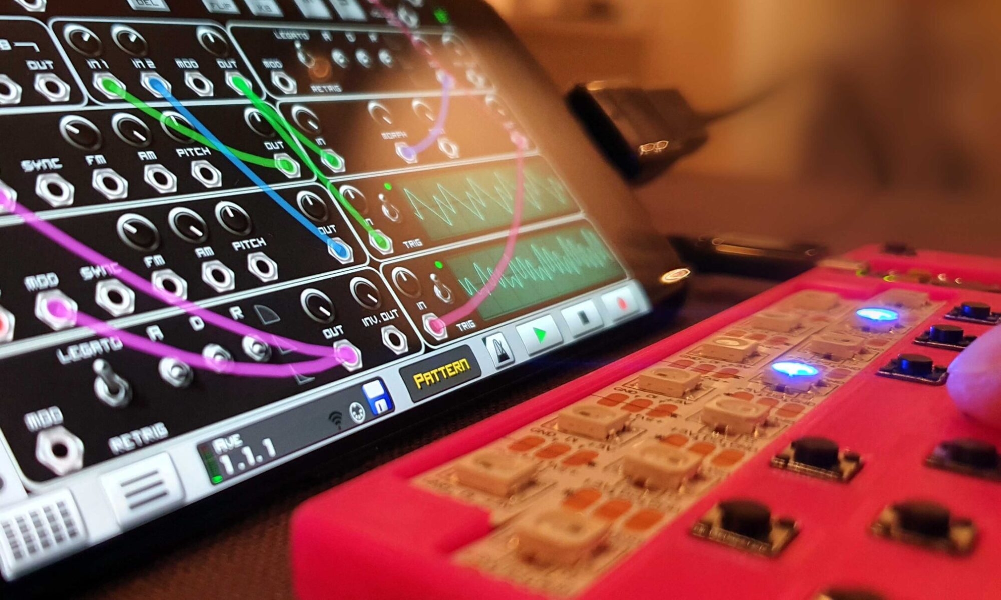
- Connect a patch cable between out1 and in 1 on the module. You will now see two saw tooth signals on the display; one for the input and one for the output.
- Tune the offset until the middle of both curves overlap.
- Tune the attenuation until the height of both curves overlap.
- Note that the offset is affected by the attenuation so you need to iterate between both potentiometers until the cyan curve is fully hidden by the magenta.
Repeat the steps above (but switch the menu and patch cable to in 2 :)
Development
After building the MIDI enabled LEET keyboards I wanted to build something that generated sounds. Eurorack has always fascinated me, but since they are quite expensive, I have never got the opportunity to play with it. What if I could simplify the design and make something less expensive…? I quite early decided that I wanted to use a digital module with AD and DA conversions. The main reason being to make it generic, but also to achieve better frequency stability and make it easier to build, as fewer components need to be sourced and soldered.
ESP32 version (dropped)
My first version relied on ESP32 with external ADC and DAC modules. It’s a powerful platform, and the use of I2S communication allows high speed conversion with high resolution. It was however difficult to find I2S ADC modules with built-in clock modules, and the device became quite complex with lots of modules and connections. I designed, routed, programmed a unit, but I realized that it was no longer the simple device that I intended to build, so I decided to ‘kill my darling’ and to start over from scratch ;(
RISC-V (Sipeed Longan Nano)
Instead of relying on the platforms that I knew, I jumped into the deep end and tested the Longan Nano board. This board is a new kid on the block with a RISC V processor that is very powerful, efficient, low cost and the Instruction set (ISA) is fully open source. The best part is that it has high speed integrated AD and DA converters. The downside? It doesn’t have much RAM, and both the instruction set and development platform (PlatformIO) was new to me. I soon realized that sample code was a scarce resource, and that some of the code was in Chinese…
I’m aware that the integrated AD & DA converters are not as good as external ones (resolution, crosstalk, SNR etc.), but for my needs they are good enough, and having them integrated simplifies the design and reduces cost. The best thing is that Longan Nano has two I2S interfaces, so it’s possible to use external components if that is required.
Code description

It took me weeks to get things running. I read the low-level manual to understand the instruction set, memory layout and peripheral descriptions. I found code snippets and combined it with custom code to handle Interrupt, AD conversion with DMA and SPI interface for the display. Everything had to be modified and it was a lot of trial and error, but eventually I had all components in place.
Timer Interrupt:
Timer6 is used to generate the sampling frequency for playback (D/A) and sampling (A/D). The 108MHz system clock is divided by 2431 to get the sampling frequency of 44.4kHz. (Slightly higher than the typical 44.1kHz used in CD players and digital audio equipment).
The timer interrupt loop is also used to sample the rotary encoder and for processing the selected Eurorack function (VCO, VCF, reverb etc.).
Main loop
The main loop is used to update the display (menu change and oscilloscope visualization)

Synchronization registers
Since the Timer6 interrupt is a separate loop to the main loop, the following global variables are used for communication between the two:
volatile int dispPos = 0; // counter for scope column (update screen when dispPos == 240)
uint8_t menuPos = 0;      // current menu position (< 127)
uint8_t menuUpd = 1;      // signals if menu was updated (=>redraw display)
float phaseC = 0;         // phaseCount | stepsize within one period (0-65535). frequenzy = xStep * 44100 / (2*65536)
uint8_t quantized = 0;    // quantize CV input of module?
uint8_t scopeTrig = 0;    // flag to init scope sampling
Phase counter
The phase counter is used for rendering waveforms for the oscillators. I started using 16-bit unsigned integer (uint16_t => 0-65535) to represent one period/phase rotation, but since the notes are logarithmical, this resulted in high resolution for the higher frequencies, but low resolution for the lower frequencies. When I realized that the CPU had enough power to use floating point arithmetic in the timer interrupt routine, I switched to floats, but kept 0-65535 as period length (could also be 0 to 1, 0 to 2pi or 0-360…).
Dynamic range of ADC and DACs
Both the input attenuator of the ADC and output amplifier of the DAC are tuned to handle 21.33VPP (-10.67V to +10.67V) with 12 bits resolution. This allows the module to be generic at the cost of a bit for a dedicated CV input. I think that the resolution is good enough when each volt has 192 AD steps. If voltage is used to generate or read CV (1V/octave), each note has 16 AD steps (minus noise).
AD2048 (0x800) corresponds to 0V, 128 (0x80) corresponds to -10V and 3968 (0xF80) corresponds to +10V. Please note that the output amplifier is an inverting type, so a separate function is used to subtract the values from 4095 before updating the DAC.
DMA
ADC0 is used to sample both input channels and the three potentiometers. Instead of doing this with a timer interrupt, DMA0 is used to load their values into RAM, which is then processed by the Timer6 interrupt routine.
The AD sampling time can be set to tune accuracy vs speed, and if I understand the timing correctly, an ADC_SAMPLETIME_13POINT5 on all 5 channels results in 41.4+12.5=54 cycles =5uS *5=20us => 50.1Hz. Since this is higher than the sampling frequency (44.4kHz) five new sampled values are ready to read at each Timer6 interrupt.
SPI:
The CPU is using SPI1 for communication with the TFT-display (SPI0 would interfere with precious ADC and DAC pins). But SPI1 shares pins with the SD card and this might be a problem as the display module is lacking CS, so SD access risk writing garbage to the display. There is however no risk of accidental writing to the SD since the SD card has CS. A display disable and/ or a forced display update after each SD Card operation mitigates this problem.
DMA could be used for update but doesn’t add much value as there is not enough RAM to hold the full display, and generating display content consumes most time anyway. To get decent framerates with the few instructions left between the timer interrupts, only changes to the display are updated in the main loop.
Design
When I had the fundamental functions in place I could focus on the physical layout of the unit. I started to develop a rather complicated 3DPCB (3D printed circuit board) with 6 levels of routing (3 units). It worked, but was almost as tricky to assemble as it was to design. This experience gave me a better understanding of the challenge and allowed me to optimize design and routing: My second version only needed 4 layers (2 units). The unit takes up 6HP and the connectors and potentiometers are evenly distributed. I integrated plastic clips to allow several units to be snapped together without the need of expensive Eurorack boxes (but those can of course be used if preferred). I also designed support structures and a press-fitted clip that works with wooden (or plastic) endcaps.

I think that a project like this is pushing the limits of the 3DPCB concept. There are lots of connections and complicated stacking of components and wires in three dimensions. The modules are working, but the assembly is quite complex and takes around one hour per module (even after making several units). The worst thing is that the package is soldered together which makes fixing a bad connection or other problems inside the unit quite tricky.
As stated earlier, for this project a traditional PCB is probably the better option. A friend routed a PCB version (with two PCBs) that makes the modules easier to replicate.
Hardware design
The design is deliberately as simple as possible. Fewer components mean easier to assemble, lower cost (and less noise ;)

Power
A miniature DC/DC module converts +12V to 3.3V suitable for the display- and the CPU-module. This can be replaced by a LDO with less noise, but the power efficiency becomes poorer with such a large voltage drop, and since the switching frequency is in the MHz range, the audible noise is insignificant. The PCB version has support for both a fixed and variable version (I recommend the smaller fixed version).
DAC amplification

A dual TL072 op-amp is amplifying the outputs from the two DACs. Instead of using four fixed high precision resistors to control bias and amplification, two trim pots are used per channel. This allows the unit to be precision tuned, but also keeps the BOM shorter and simplifies the design since identical components can be used. Note that I have not added capacitors over the feedback signal to reduce oscillation of fast transitions. I’m sure people will claim that they must be added, and please do if you prefer, but I think it’s overkill ;)
ADC attenuation

It’s standard procedure to use an op-amp before the ADC to attenuate the signal and make the input high-impedance, but the voltage divider of the op-amp will make the input dependent of the resistance of the output stage of the other module. This can be avoided by adding an additional voltage follower, but this is rather uncommon even in professional equipment, and since I wanted to keep things simple, I simply skipped all op-amps on the input stage. The ADC is high impedance in itself and by tuning the sampling time of the ADC, all that is required are two potentiometers, one to attenuate 21.33Vpp to 3.3Vpp and one to lift it to 0 to 3.3V. The design has no external clamping diodes, so avoid connecting voltages outside -12V to 12V.
Ensure that potentiometers are in “middle” position before initial tuning. If attenuation is tuned all the way towards ground and bias is tuned towards VCC, you will short-circuit the module and probably fry the pots… (this could be prevented with an external resistor, but since it’s never a problem when you tune or use it, I didn’t see the need).
Scripts
I have created a few Python scripts that offloads the microprocessor and generates logarithmic lookup tables, icons and menu system. They are relying on cut-and-paste at the moment (project files would be better).
The LUTs are straight forward and converts AD values corresponding to CV frequencies to phase steps. (Note that I have not tuned the LUT to compensate for possible nonlinearity of the unit).
I wanted to use graphics to highlight the selected function of the module. To fit different icons in the memory I wrote a custom compression algorithm that is more efficient than typical file formats for two colour icons. It xor compresses the rows and then uses a tuned RLE compression to reduce the size further. The script generates raw, gif, png and jpg to compare the file size.
The menu system became difficult to manually create, so I wrote a script that converts a tab indent menu system to the format used by the device. 0-127 is used for internal index and references while 128-255 is used to select mode/function of the module. It creates the arrays for names and navigation, but also #define statements for code reference to avoid hard coded indexes. (I have not used escape characters, so some characters are prohibited).

Future development
My goal for the project was to build a working system with basic functions. I have reached that stage, and I think it’s mature enough to share it so others can test, use and improve it. There are lots of things that can be enhanced, here are some I have considered:
- Improve existing functions; I’m sure that people with more Eurorack experience have recommendations on how to enhance the existing functions of the unit. One low hanging fruit is the delay that needs better controls to adjust buffer length and feedback.
- Improve UI
- Remove debug data
- Describe ports & pots
- Highlight frequency and note of VCOs
- Screensaver…
- New functions
- Gate and CV Sequencer (using the TFT)
- Sampler (using SD card)
- Clock divider
- Glide
- Quantizer
- Arpeggiator
- Math and logic units
- Etc.
- Clean up code and integrate MIDI support (now separate code base)
I hope that others will continue the development and take the project in new directions. I might take on one some of the above ideas. Please let me know what you are missing – if several people request the same feature, I will try to prioritize them ;)

Download project files

All files required for this project are available at this GitHub repository:
https://github.com/vonkonow/LEET-Modular
License

This project is open source under MIT License
(Attribution is optional, but appreciated /Johan von Konow ;)
It look great !
I don’t find the white modules in the repo. Converting usb-c to eurorack power is cool too !
The only thing missing right now is midi-to-cv module I think. One can use them as sequencer and more.
… Do you still have fun with your creations or the hype goes down ?
Thanks
Still an ongoing project – I have been focusing on building more modules and an euro rack case (almost there ;)
I will publish the PSU and the passive attenuator, great that someone is asking for it!
There is actually working code for midi (over USB-C) to CV, it is rudimentary, but works. Check out https://github.com/vonkonow/LEET-Modular/tree/main/code
Great ! Does it happen that you make kits of your work (Tindie like) ? I have to say, you make a beautiful work for your projects AND descriptions of it, there is only a micro-step (the kits) to convince people to make all your projects at home !
It’s wonderfull how simple the end-projects look like, but how hard you had to think and try before sharing them.
I’ve started some, used a lot of your 3dprinted pcb concept on my projets and never miss a occasion to share your website when i’m training people to 3dprinting (my daily work). But I guess that it’s hard to see that your work make people dreaming if nobody write about it ;-)
Thank you for the kind words, I’m glad to hear that the projects are inspiring other builders out there :)
A kit would be nice, but I think the project needs to be more mature since buyers would have high expectations. I tend to publish my projects early to see if they get any feedback and to allow others to improve and add functionality. Maybe one day…
Hey! I am going to be building some of these. I laser cut my own panels, but I can’t seem to find a file on the Github for a face plate. Is there something you could add there? Like the STEP and STL for the 3D printed one shown in some of the pictures? Thanks!
Oh, I was able to get it out of the Gerber file. Another question, is there a more in-depth guide to loading the code onto the board? I am having trouble understanding exactly what to do from the sources I can find.
Sorry for spamming this comment section, it seems like the Code folder is missing the platformio.ini file that is needed for Platformio to be able to properly recognize the code.
Thank you, missed that. Create an empty platform.ini file and add this:
[env:sipeed-longan-nano]
platform = gd32v
board = sipeed-longan-nano
framework = gd32vf103-sdk
upload_protocol = dfu
I wrote this on the github page:
I used Platform IO in visual studio code. In theory it is possible to use Arduino IDE, but I haven’t tried, and I don’t know if programming would work. Unfortunately, It is a bit tricky to program the first time, hopefully it is better today, but I remember spending some time googling, downloading and installing different USB drivers…
Hope it helps, good luck!
I just updated github with 3D models for front panel and front-, middle- and back- covers.
Hope it work as basis for laser cutter. I would love to see the result!
Awesome! Thank you very much. That back cover is a really cool idea!
Here is a preview of the panel I made. Needs a little more clean up on the paint though: https://photos.app.goo.gl/ZpVhBXpjdLgAjGCB6
That looks great! Love the textured surface.
Did you use support for the painted recesses?
Was the tuning of the pots ok? I have improved the process a bit since, but the code is still a work in progress..
The microcontroller looks like it’s hard to come by cheaply. Do you think I could use a w806 microcontroller
Great question, the functionality will be limited:
* It certainly won’t fit
* The MIDI over USB functionality will not work with ch340
* I don’t see any DACs, only pwm…
* Only 4 ADCs
The spec seems somewhat similar so it really depends on the toolchain.
If you have a board, you can always try to compile and upload to see if parts of it works…
Great work. Would really like to see some more demos of these… would also like to be able to get 2-4 of these… but I have no skills around ordering from a Gerber… solder, sure… “from scratch” not so much. Very cool… and if anyone is interested in doing a run… let me know!