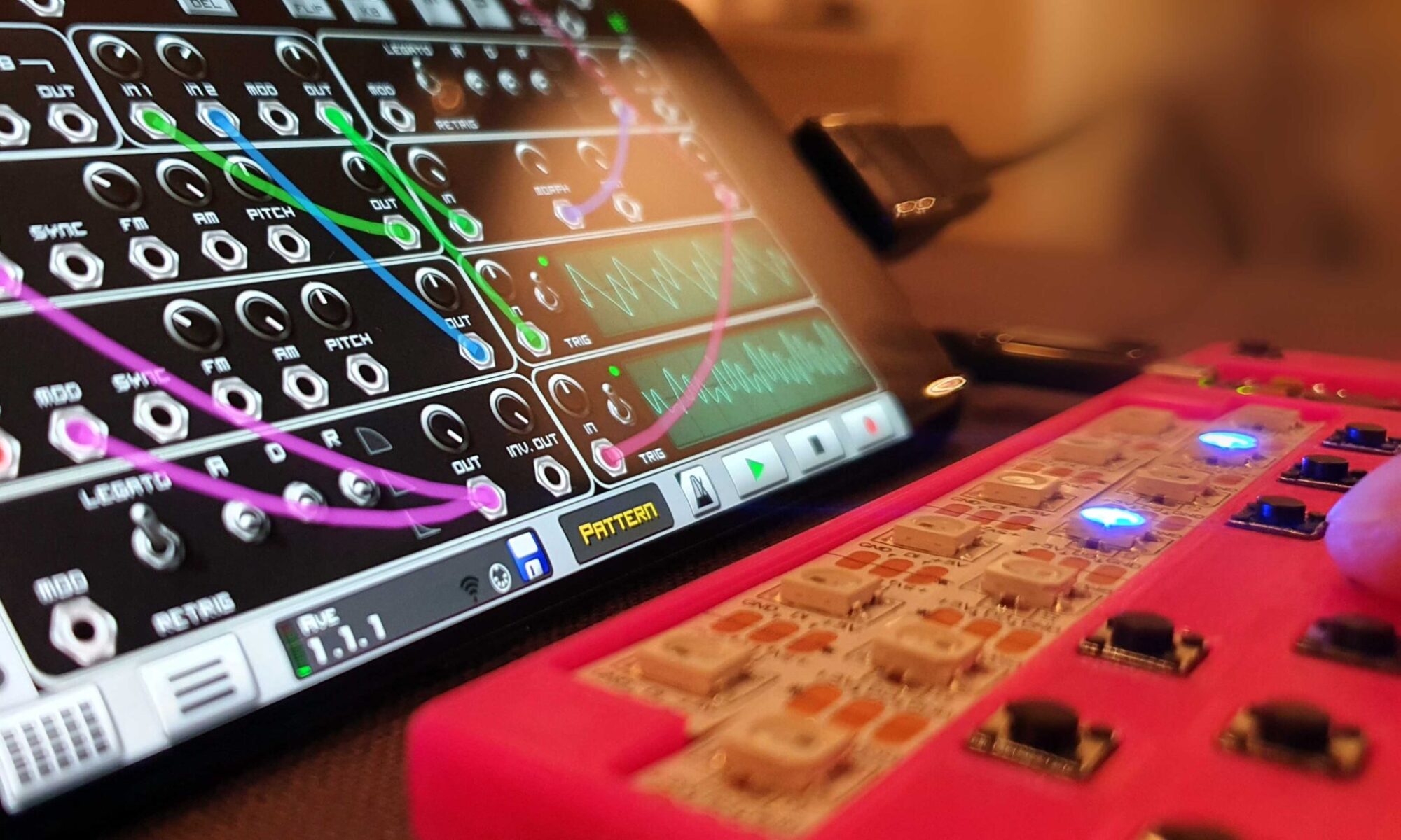
Leet AI – Wireless Synthesizer Ensemble with AI-powered inspiration

Introduction

Many synthesizers are powerful (and complicated) “all in one” units that can do almost anything. I wanted to test the opposite where several units (one for each instrument) work together as an orchestra.

Leet AI is a concept for a miniature synthesizer with the following design goals:

  • Cute, small, playful and cheap (so you can have one for each instrument)
  • Open source and customizable (programmed in python with COTS modules)
  • Easy to use (the display shows current mode and options – no need for strange key combinations)
  • Wireless communication and battery powered
  • AI enabled (so it can generate new melodies for inspiration)

Please note that Leet AI is a concept that is missing lots of features, but it is mature enough to demonstrate the overall idea. If it gets good feedback, I will probably continue to work on it, and since it is open source – anyone can contribute :)

The synth is medium difficult to build – you need to solder SMD components and have access to a 3D printer.

Spec:

  • 86 x 60 x 15 mm (smaller than a deck of cards)
  • 16 keys with RGB LEDs
  • powerful microprocessor running circuit python (ESP32-S2)
  • 1.8” color display (160×128 pixels)
  • 1000mAh rechargeable LiPo battery
  • high quality 112dB SNR DAC
  • low latency wireless communication (ESP-now)
  • MIDI in/out over USB-C
  • 2 rotational magnetic encoders with dual tilt navigation

Design process:

Leet AI is combining the best parts of three other projects – leet, leet modular and ChipChamp. When I played with those projects, I learned a lot and gained enough confidence to take the next step. The synth is based on circuit python, making it easy to modify and write new functions. When connected to a computer (over USB-C) the synth appears as an USB drive (allowing you to modify the code directly).

AI muse

I thought it would be nice if the synth could use AI to propose different melodies, tracks and drum patterns as inspiration. Instead of doing inference on the device – it connects (wirelessly) to a server that does the heavy lifting. The server runs a modified version of the getMusic project from Microsoft research – a diffusion model that that can generate new tracks to an existing midi file. It works quite well but like the early image generation diffusion models it requires some patience and most results are so-so, but every now and then something beautiful emerges and you get really amazed. This is still an early stage of generative AI and I’m convinced that the result will improve with better models in the future (if you know your stuff – you can even train it on your favorite music :)

The demo

I asked chatGPT write a chord progression program in python, based on a tunable Markov chain. The generated midi progression is used for the bass track. Another program composed a simple arpeggio that followed the progression and those two tracks were repeated six times. I used a midi editor to tweak the bass and removed the arpeggio in the intro and bridge. The AI was modified so it composed 20 versions of the lead and drum track. 15 versions were crap, 3 ok and 2 were great. I combined the two and Robert is your mother’s brother!

AI generated score

Since the audio generation has more to give – I rendered a final version of the song in Ableton. It needs more love (and skill) but is good enough to show the potential… The video shows how one unit acts as a conductor (keeping the other units in sync, outputting MIDI and rendering audio), while the other units correspond to each instrument, bass, lead, piano and drum.

Prototype

For the synth I started by adding a I2S DAC to a ChipChamp and experimented with different python libraries until it could play music. I combined the audiocore library for drum samples with synthio for wavetable synthesis.

I spent a lot of time tuning the graphics to make the piano roll animation. There was not enough processing power to move around the sprites, so I created a static grid where the sprites are turned on and off depending on the time in the melody. This works quite ok, but it would be nice with an optimized library with smother animation and where the height of the sprites is depending on the note duration…

Another rabbit hole was the wireless communication and time synchronization between the units. A lightweight custom protocol is used with of ESPnow (sending single Wi-Fi packets). Commands are broadcasted to all units and some packets are addressed to a certain instrument. When a device is powered on it sends a pair request to the conductor that then transmits all events for the instrument in the song.

Design

Once I got the basic functions working, I set the design goals and did a lot of sketches in Rhino with different components to find the right form factor.

I ended up with a single octave design with a display and two encoders for navigation and tuning. I think it looks like a cute version of a QY70.

A two-octave version with a wide OLED screen was considered, but I like the idea of stacking several units to cover several octaves. I used Inkscape to evaluate different design ideas and then completed the final 3D-model in Rhino.

Custom encoders

To keep it compact I used a traditional PCB instead of the 3DPCB. I did the schematics in KiCad and routed a first version with 12 keys (one octave). I didn’t want any protruding parts so I replaced the traditional mechanical rotation encoder with a magnetic version, but I also complemented the rotation with two keys so it could be used for menu navigation (next, prev, select and back). A 3D printed carrier holds a bearing in place and the flexible arms allows the bearing to tilt, pressing the upper or lower switches. I lost count of the number of iterations I went thru, but eventually it worked just as I had hoped for.

Since the AS5600 sensor have a fixed i2c address, I used the analog mode so I only needed a single I/Os for the position. When I briefly studied the datasheet, I thought I could disable the 10-LSB hysteresis in the configuration register, but later realized that the register only affects the digital mode, not the analog.  This meant that there is a gap in the beginning and end of each rotation, which was quite annoying.

The modules for the LiPo charger and the magnetic encoders were too big to fit, so I replicated their design on the PCB. Instead of ordering the components separately, I desolder and resolder the components from the modules.

Dual tilt, ball bearing magnetic encoders

Second version – more keys

I planned to make two versions of the synth, one with a single octave layout, and one with a 16 step sequencer. After building the first version I realized that if I staggered 16 keys it would cover both needs. It’s one of those ideas that is so simple that it’s embarrassing that I didn’t think of it immediately…

I made a second version with 16 keys and replaced the analog encoder output with dual bit banged i2c interfaces. Since this version is slightly wider, I could fit the charger module inside making it easier to build. The synth is slightly smaller than a deck of cards and I think I like the proportions of the second version even more.

position of modules
Schematic
PCB design
3D model front
3D model back
COTS modules: I2S DAC and ESP32-S2 mini, battery & charging

Sound generation

The synth is using the excellent synthio library for audio output. Each synth can use semi modular synthesis, samples or wavetables. When the Boss unit is rendering all the instruments, it is limited to fixed sample playback (for drums) and wavetable generation due to performance. To be honest, the generated sound is ok to play around with melodies, but nowhere near the fidelity required for production. If I learn how to write my own python libraries in the future, an optimized audio library that can mix different samples with different pitch would be powerful.

AI assisted development

Since the synths appears as a USB drive when connected to a computer, it is super easy to use AI code assistants like cursor.sh or continue.dev. Simply select the synth in the editor and tell the agent what you would like to develop. I used it a lot to improve the code structure and error handling. It is easy, powerful, and fun (especially when it occasionally goes off the rails :)

Future development:

There are tons of things to implement. I don’t recommend building it at this stage since almost everything is hard-coded for the demo and the unit is quite useless without implementing:

  • Optimized audio (increase sample rate, control sample pitch, reduce CPU load and jitter)
  • Support for creating and editing melodies and patterns
  • Optimized graphic libraries – more fluent animations with reduced cpu load
  • Selecting different instrument sounds
  • Tuning parameters like velocity, bend, swing, ADSR and filters
  • Various bug-fixing and test automation
  • Stacked octave mode (several units form a single synth with more octaves)
  • Wi-Fi connection to a generative AI server (done manually for the demo)
  • Maybe a version with built in speaker?
  • Add support for the AMY synth library?
LeetAi fits perfectly in temu card containers and cable storage bag.

Prices including freight (2025-01-05)

  • 43           esp32s2 mini (129 | 3) (Amazon)
  • 29           magnetic encoders (116 | 4) (Amazon)
  • 26           ball bearings (105 | 10) (Amazon)
  • 25           switches (100 | 5) (Amazon)
  • 20           LEDs (78 | 100) (Amazon)
  • 43           LCD (128 | 3) (Amazon)
  • 22          battery charger (89 | 6) (Amazon)
  • 10          battery (17 | 4) (Ali express 803040 1000mah)
  • 25           DAC (100 | 4) (Ali express PCM5102A)
  • 10           misc. diodes, power switch and filament
  • 10          PCB (40 | 5) (JLCPCB)
  • total: 263 SEK => $24

Download project files

All files required for this project are available at this GitHub repository:
https://github.com/vonkonow/LeetAI

License

This project is open source under MIT License
(Attribution is optional, but appreciated /Johan von Konow ;)

LEET modular – a multifunctional Eurorack module

This is my contribution to the Eurorack system.  LEET modular is versatile, easy to build, affordable and powerful. It is a multifunctional module that offers a variety of different functions and by patching several units, advanced sounds and music can be generated.  It’s entirely open source and hacking is encouraged.

25 second demo of LEET modular

Specification:

  • 6HP wide (30.48 mm)
  • 2 generic inputs
    • -10V to 10V range (20VPP)
    • 44kHz, 12-bit AD
    • suitable for CV, audio and digital (gate) input
  • 2 generic outputs
    • -10V to 10V range (20VPP)
    • 44kHz, 12-bit AD
    • suitable for CV, audio and digital (gate) output
  • 1 display
    • 1.3” full color IPS TFT display (261 DPI)
    • 240×240 pixels
    • Used to show information such as selected function, menu system, sampled values and oscilloscope for incoming and outgoing signals.
  • 1 rotary encoder for menu navigation
  • 3 potentiometers to configure and tune selected function
  • Requires +12V (36mA) and -12V (5mA) Eurorack connector (small/10pin or large/16pin).
    (I have also built an open source USB-C power module)
PCB version of a LEET modular unit (without frontpanel)

Why:

There are a lot of DIY/ open source Eurorack modules available. What’s special about this module is that it uses off-the-shelf modules, is easy to build (since it has few components) and cheap enough for you to make several units without investing a fortune. The built-in high quality display visualizes how the sound is generated and allows the module to be flexible and easy to use. I designed the module to be generic – this equals compromises and I’m sure some will think that the quality is not good enough for their needs. Luckily everything is open source, so feel free to adjust the module to fit your specific needs!

  • Easy to build
  • Low cost (~$15, see below)
  • Built-in display/ oscilloscope.
  • Easy to modify and hack (use it as a platform for custom modules).
  • Compact
  • Fully open source
rendering of PCB version with 3D printed spacers and frontpanel

Current implemented (rudimentary) functions:

  • VCO / Oscillators (with different waveforms, AM, FM, folding, quantization, and other features)
  • LFO
  • VCF (with a few different low pass filters)
  • Noise generator
  • Delay/ reverb
  • MIDI to CV (USB-C)
  • Initialization / Set up / trim mode (to facilitate the initial tuning of a new unit)
  • I have also built 3D printable support modules so it can be used without additional devices:
    • power module converting USB-C (5V) to the Eurorack standard (12V & -12V)
    • passive attenuator (used to drive line out / headphones)
power-, five modules, attenuator and patch cables = working synth ;)

Hack me

The module is fully open source (MIT license) allowing you to customize it anyway you need. Here are some proposals of customizations to fit different requirements:

  • Software
    • Add new functions/ modules
    • Alter UI
    • Combine functions (like a drum module)
    • Port other open source modules
  • Hardware
    • Remove TFT (make dedicated modules instead of generic)
    • Add more inputs, buttons, pots, LEDs and sensors

Build your own

I have designed two versions of the module: The 3DPCB version (using a 3D printed part to guide wires, thus eliminating the need for a PCB order) , then I got help from a friend to design a more traditional PCB version. If you have time to wait for the PCB order, I would recommend that version as it’s easier to assemble and adjust if something is not working.

BOM (for one unit)

  • 1x 1.3” TFT display module (IPS 240x240px SPI ST7789)
  • 1x Sipeed Longan Nano RISC-V GD32VF103CBT6 MCU (128kB Flash, 32kB RAM)
  • 1x DC/DC module (fixed 3V3 AJ38, or variable MP1584EN)
  • 1x TL072 (DIP – NOT SMD)
  • 3x 10k potentiometers (Rv09 12.5mm shaft)
  • 1x Rotary encoder (15mm handle)
  • 4x 3.5mm jack sockets (different models for PCB and 3DPCB version)
  • 2x 1k resistors
  • 2x 0.1uF Capacitor
  • 1x Eurorack power connector (0.1” pin headers can be used)
  • 8x 100k Trim pots
  • 1x 40 pin 0.1” header (14 + 8 pins used)
  • 1x 40 pin 0.1” socket
  • Front panel (PCB or 3D printed)
  • 3DPCB and copper wire or PCB

Cost estimate

These are the prices I got when I bought the components from Ali express (2022-02 converted from SEK to USD without shipping and VAT, but shipping is usually included). There is a volume dependency for some components (I ordered 10 units). My first batch before the global chip shortage resulted in sub $10 total.

TFT$3.37
Longan Nano$5.77
DC/DC$0.29
TL072$0.10
Pot rv09 x3$0.48
Rotary encoder$0.48
Multi turn trimpot x8$0.67
PCB x2$0.96
3,5 mm jack sockets x4$0.96
total:$13.08
Cost estimate for PCB version

Building instructions (PCB version)

Assemble the top PCB (with the display):

  1. If you use a variable DC/DC, connect it to 12V and adjust the output to 3.3V (higher voltage might fry the display or MCU). Skip this step if you use the fixed voltage DC/DC.
  2. Solder the pin headers on the backside, then the resistors, DC/DC converter (upside down), display (with 3D printed display support), 3.5mm jacks, pots and rotary encoder.
  3. Inspect all solder joints and look for short circuits or cold solder joints.

Bottom PCB (with the microprocessor module):

  • Download the Git repo, install and configure PlatformIO, add Longan Nano support, compile, and program the MCU with a USB-C data cable.
  • Solder the CPU module to the PCB. There is a routing error in my PCB design, so three wires need to be adjusted in the current version. I used a 3D printed support and copper wire instead of a pin header (easier to adjust if something is wrong).
3d printed adapter solving the routing error on 1.0 version of longan nano (back) and 1.1v (front)
  • Solder the pin sockets on the backside, then the op-amp (verify orientation and use a socket if you want), and then solder the power pin header.
  • Ensure that the trim pots are roughly in the middle position and solder them according to this drawing (this will ensure that clockwise trimming increases voltage).
trimpot orientation
  • Inspect all solder joints and look for short circuits or cold solder joints.
  • Connect a variable power supply with current limiting and slowly increase voltage, to make sure that 3.3V is reached but not exceeded.
Soldering a module in 2.5 minutes (10x speed)

Tuning:

The inputs and outputs of the module must be tuned before the module can be used. This is to maximize the resolution of the ADC/ DACs, but it will also adjust the voltage levels so that the input is not harmful for the ADC. Note that trim pots are somewhat sensitive to temperature, so it should preferably be done in room temperature. We start with the output:

Trim the output:

Two potentiometers are used to adjust the amplification and offset for each channel.

  1. Connect a patch cable to channel 1 and attach a voltmeter to the other end (DC mode).
  2. Attach the module to Eurorack power and use the rotary encoder to navigate to Settings/Calibrate/0V (and push the encoder to set the output). 
  3. Adjust the offset voltage until the voltmeter reads 0V.
  4. Navigate to 10V and adjust the amplification pot until the voltmeter reads 10V.
  5. Navigate to -10V and note the voltage. You will probably need to tune both the offset and amplification; if for example the output reads -8V you should adjust the offset to -9V ((10+8)/2) and then adjust the amplification until you get -10V.
  6. Navigate back to +10V and iterate adjustment if needed.

Repeat the steps above for the second output.

Trim the input:

The input needs to be trimmed so that the signal is attenuated (reduced) to levels accepted by the microprocessor (0-3.3V). Note that you risk frying the ADC input if it’s not tuned properly. Also note that you can short the potentiometers if they are tuned to the extreme ends, avoid this by following the steps below:

  1. Navigate to Settings/Calibrate/out1 to in 1.
  2. Connect a patch cable between out1 and in 1 on the module. You will now see two saw tooth signals on the display; one for the input and one for the output.
  3. Tune the offset until the middle of both curves overlap.
  4. Tune the attenuation until the height of both curves overlap.
  5. Note that the offset is affected by the attenuation so you need to iterate between both potentiometers until the cyan curve is fully hidden by the magenta.

Repeat the steps above (but switch the menu and patch cable to in 2 :)

Development

After building the MIDI enabled LEET keyboards I wanted to build something that generated sounds. Eurorack has always fascinated me, but since they are quite expensive, I have never got the opportunity to play with it.  What if I could simplify the design and make something less expensive…? I quite early decided that I wanted to use a digital module with AD and DA conversions. The main reason being to make it generic, but also to achieve better frequency stability and make it easier to build, as fewer components need to be sourced and soldered.

ESP32 version (dropped)

My first version relied on ESP32 with external ADC and DAC modules. It’s a powerful platform, and the use of I2S communication allows high speed conversion with high resolution. It was however difficult to find I2S ADC modules with built-in clock modules, and the device became quite complex with lots of modules and connections. I designed, routed, programmed a unit, but I realized that it was no longer the simple device that I intended to build, so I decided to ‘kill my darling’ and to start over from scratch ;(

RISC-V (Sipeed Longan Nano)

Instead of relying on the platforms that I knew, I jumped into the deep end and tested the Longan Nano board. This board is a new kid on the block with a RISC V processor that is very powerful, efficient, low cost and the Instruction set (ISA) is fully open source. The best part is that it has high speed integrated AD and DA converters. The downside? It doesn’t have much RAM, and both the instruction set and development platform (PlatformIO) was new to me. I soon realized that sample code was a scarce resource, and that some of the code was in Chinese…

I’m aware that the integrated AD & DA converters are not as good as external ones (resolution, crosstalk, SNR etc.), but for my needs they are good enough, and having them integrated simplifies the design and reduces cost. The best thing is that Longan Nano has two I2S interfaces, so it’s possible to use external components if that is required.

Code description

included files in main.cpp

It took me weeks to get things running. I read the low-level manual to understand the instruction set, memory layout and peripheral descriptions. I found code snippets and combined it with custom code to handle Interrupt, AD conversion with DMA and SPI interface for the display. Everything had to be modified and it was a lot of trial and error, but eventually I had all components in place.

Timer Interrupt:

Timer6 is used to generate the sampling frequency for playback (D/A) and sampling (A/D). The 108MHz system clock is divided by 2431 to get the sampling frequency of 44.4kHz. (Slightly higher than the typical 44.1kHz used in CD players and digital audio equipment).

The timer interrupt loop is also used to sample the rotary encoder and for processing the selected Eurorack function (VCO, VCF, reverb etc.).

Main loop

The main loop is used to update the display (menu change and oscilloscope visualization)

the high resolution IPS TFT looks stunning

Synchronization registers

Since the Timer6 interrupt is a separate loop to the main loop, the following global variables are used for communication between the two:

volatile int dispPos = 0; // counter for scope column (update screen when dispPos == 240)
uint8_t menuPos = 0;      // current menu position (< 127)
uint8_t menuUpd = 1;      // signals if menu was updated (=>redraw display)
float phaseC = 0;         // phaseCount | stepsize within one period (0-65535). frequenzy = xStep * 44100 / (2*65536)
uint8_t quantized = 0;    // quantize CV input of module?
uint8_t scopeTrig = 0;    // flag to init scope sampling

Phase counter

The phase counter is used for rendering waveforms for the oscillators. I started using 16-bit unsigned integer (uint16_t => 0-65535) to represent one period/phase rotation, but since the notes are logarithmical, this resulted in high resolution for the higher frequencies, but low resolution for the lower frequencies. When I realized that the CPU had enough power to use floating point arithmetic in the timer interrupt routine, I switched to floats, but kept 0-65535 as period length (could also be 0 to 1, 0 to 2pi or 0-360…).

Dynamic range of ADC and DACs

Both the input attenuator of the ADC and output amplifier of the DAC are tuned to handle 21.33VPP (-10.67V to +10.67V) with 12 bits resolution. This allows the module to be generic at the cost of a bit for a dedicated CV input. I think that the resolution is good enough when each volt has 192 AD steps. If voltage is used to generate or read CV (1V/octave), each note has 16 AD steps (minus noise).

AD2048 (0x800) corresponds to 0V, 128 (0x80) corresponds to -10V and 3968 (0xF80) corresponds to +10V. Please note that the output amplifier is an inverting type, so a separate function is used to subtract the values from 4095 before updating the DAC.

DMA

ADC0 is used to sample both input channels and the three potentiometers. Instead of doing this with a timer interrupt, DMA0 is used to load their values into RAM, which is then processed by the Timer6 interrupt routine.

The AD sampling time can be set to tune accuracy vs speed, and if I understand the timing correctly, an ADC_SAMPLETIME_13POINT5 on all 5 channels results in 41.4+12.5=54 cycles =5uS *5=20us => 50.1Hz. Since this is higher than the sampling frequency (44.4kHz) five new sampled values are ready to read at each Timer6 interrupt.

SPI:

The CPU is using SPI1 for communication with the TFT-display (SPI0 would interfere with precious ADC and DAC pins). But SPI1 shares pins with the SD card and this might be a problem as the display module is lacking CS, so SD access risk writing garbage to the display. There is however no risk of accidental writing to the SD since the SD card has CS. A display disable and/ or a forced display update after each SD Card operation mitigates this problem.

DMA could be used for update but doesn’t add much value as there is not enough RAM to hold the full display, and generating display content consumes most time anyway. To get decent framerates with the few instructions left between the timer interrupts, only changes to the display are updated in the main loop.

Design

When I had the fundamental functions in place I could focus on the physical layout of the unit. I started to develop a rather complicated 3DPCB (3D printed circuit board) with 6 levels of routing (3 units). It worked, but was almost as tricky to assemble as it was to design. This experience gave me a better understanding of the challenge and allowed me to optimize design and routing: My second version only needed 4 layers (2 units). The unit takes up 6HP and the connectors and potentiometers are evenly distributed. I integrated plastic clips to allow several units to be snapped together without the need of expensive Eurorack boxes (but those can of course be used if preferred).  I also designed support structures and a press-fitted clip that works with wooden (or plastic) endcaps.

3Dprinted front panels as option to aluminium or PCB

I think that a project like this is pushing the limits of the 3DPCB concept. There are lots of connections and complicated stacking of components and wires in three dimensions. The modules are working, but the assembly is quite complex and takes around one hour per module (even after making several units). The worst thing is that the package is soldered together which makes fixing a bad connection or other problems inside the unit quite tricky.

As stated earlier, for this project a traditional PCB is probably the better option. A friend routed a PCB version (with two PCBs) that makes the modules easier to replicate.

Hardware design

The design is deliberately as simple as possible. Fewer components mean easier to assemble, lower cost (and less noise ;)

Schematics of the module, showing the separation between the top and bottom PCB.

Power

A miniature DC/DC module converts +12V to 3.3V suitable for the display- and the CPU-module. This can be replaced by a LDO with less noise, but the power efficiency becomes poorer with such a large voltage drop, and since the switching frequency is in the MHz range, the audible noise is insignificant. The PCB version has support for both a fixed and variable version (I recommend the smaller fixed version).

DAC amplification

A dual TL072 op-amp is amplifying the outputs from the two DACs. Instead of using four fixed high precision resistors to control bias and amplification, two trim pots are used per channel. This allows the unit to be precision tuned, but also keeps the BOM shorter and simplifies the design since identical components can be used. Note that I have not added capacitors over the feedback signal to reduce oscillation of fast transitions. I’m sure people will claim that they must be added, and please do if you prefer, but I think it’s overkill ;)

ADC attenuation

It’s standard procedure to use an op-amp before the ADC to attenuate the signal and make the input high-impedance, but the voltage divider of the op-amp will make the input dependent of the resistance of the output stage of the other module. This can be avoided by adding an additional voltage follower, but this is rather uncommon even in professional equipment, and since I wanted to keep things simple, I simply skipped all op-amps on the input stage. The ADC is high impedance in itself and by tuning the sampling time of the ADC, all that is required are two potentiometers, one to attenuate 21.33Vpp to 3.3Vpp and one to lift it to 0 to 3.3V. The design has no external clamping diodes, so avoid connecting voltages outside -12V to 12V.

Ensure that potentiometers are in “middle” position before initial tuning. If attenuation is tuned all the way towards ground and bias is tuned towards VCC, you will short-circuit the module and probably fry the pots… (this could be prevented with an external resistor, but since it’s never a problem when you tune or use it, I didn’t see the need).

Scripts

I have created a few Python scripts that offloads the microprocessor and generates logarithmic lookup tables, icons and menu system. They are relying on cut-and-paste at the moment (project files would be better).

The LUTs are straight forward and converts AD values corresponding to CV frequencies to phase steps. (Note that I have not tuned the LUT to compensate for possible nonlinearity of the unit).

I wanted to use graphics to highlight the selected function of the module. To fit different icons in the memory I wrote a custom compression algorithm that is more efficient than typical file formats for two colour icons. It xor compresses the rows and then uses a tuned RLE compression to reduce the size further. The script generates raw, gif, png and jpg to compare the file size.

The menu system became difficult to manually create, so I wrote a script that converts a tab indent menu system to the format used by the device. 0-127 is used for internal index and references while 128-255 is used to select mode/function of the module. It creates the arrays for names and navigation, but also #define statements for code reference to avoid hard coded indexes. (I have not used escape characters, so some characters are prohibited).

Future development

My goal for the project was to build a working system with basic functions. I have reached that stage, and I think it’s mature enough to share it so others can test, use and improve it. There are lots of things that can be enhanced, here are some I have considered:

  • Improve existing functions; I’m sure that people with more Eurorack experience have recommendations on how to enhance the existing functions of the unit. One low hanging fruit is the delay that needs better controls to adjust buffer length and feedback.
  • Improve UI
    • Remove debug data
    • Describe ports & pots
    • Highlight frequency and note of VCOs
    • Screensaver…
  • New functions
    • Gate and CV Sequencer (using the TFT)
    • Sampler (using SD card)
    • Clock divider
    • Glide
    • Quantizer
    • Arpeggiator
    • Math and logic units
    • Etc.
  • Clean up code and integrate MIDI support (now separate code base)

I hope that others will continue the development and take the project in new directions. I might take on one some of the above ideas. Please let me know what you are missing – if several people request the same feature, I will try to prioritize them ;)

bare PCB and version with 3D printed cover and 6HP front panel

Download project files

All files required for this project are available at this GitHub repository:

https://github.com/vonkonow/LEET-Modular

License

This project is open source under MIT License
(Attribution is optional, but appreciated /Johan von Konow ;)

SokoDay – easy to pick up, hard to put down.

Description

SokoDay downloads three new Sokoban puzzles every day from a server. One short, one medium and one long (referring to number of moves to solve the level). You can build your own device with a 3D printer, soldering iron and a handful of components. 

Sokoban is an addictive game where you push boxes to designated areas. It has been praised for being “pure and simple, very playable and mentally challenging”.

a 40 sec video showing how a medium level is loaded and solved
  • Fun and challenging to play
  • Easy to build
  • No PCB needed – 3D print two parts and connect the components using 3DPCB
  • Only a handful of components needed
  • Open source and easy to hack (write new games, change hardware etc.)
  • Use of modules simplifies design and removes the need for soldering tiny components
  • Portable – built in Li-ion battery and USB-C charging circuit
  • Wi-Fi connection to server with over 10 000 levels
  • Emulator avaliable

Idea

One day I realized that a Sokoban game could be played using a low resolution RGB matrix as display. Different colors could represent the player, boxes, walls and goals. It was such a simple idea that I expected to find several projects when I searched for it online. When I couldn’t find any, I was excited to start the development. Little would I know that I would spend several months completing and tuning the project until I was satisfied with the result. It was however a very fun project, covering electronics, embedded programming with Wi-Fi connections, industrial design, web servers and lots of scripts to gather, filter, sort and solve the different Sokoban levels.

Instead of letting the players choose from ten thousand challenges, I thought ‘less is more’ and got the idea to present a new challenge every day instead. This was in line with my ambition to make the game simplistic and clean, while hiding the backend from the user.

Sokoban game manual

  Red pulsating LEDPlayer
  Pink LEDWall
  Green LEDTarget
  Blue LEDBox (on floor)
  Cyan LED (blue + green)Box on target
  Yellow pulsating LED (red+ green)Player on target
  Black (LED off)Empty floor
Display color explanation
  • Use the four switches to move the player
  • A box can only be pushed (not pulled)
  • Push the boxes to their designated areas (targets)
  • When all boxes are on top of the goals the game is won

Note that there is no undo, you must reload the level to start over – “You don´t play Sokoban because it is easy, you play it because it is hard ;)”. This forces you to think several steps ahead instead of trial and error. It can be frustrating, but it becomes more rewarding.

You select one of three daily levels by holding down the navigation keys during power on.

  • Pressing up during power on loads the short level
  • Pressing right during power on loads medium level and
  • Pressing down during power on loads the long level

By pressing left and then one of the other keys (short, medium, long) during power up you can change the default level to be loaded. This setting is stored in nonvolatile memory and will be used during a normal power up (without navigation key). This is useful to match your preferred level or if you e.g. print several games, each with one level length.


Emulator

http://vonkonow.com/sokoplay/

If you are unsure if this game is for you, I built an html-based emulator, allowing anyone to test the game in a web browser. The daily levels are identical with the ones on the handheld device and it also shows map credits and solution. Test the game and decide if it is for you, if you like it, I highly recommend building the handheld version which provides a better experience ;)

BOM

  • 1x D1-mini board (ESP8266 based, Wemos Lolin or compatible) – This module provides both the CPU/ brain of the game and the wireless access
  • 1x WS2812 8×8 RGB LED Matrix (PCB, not FPC)
  • 1x charging module (with USB-C connection)
  • 1x Li-ion battery 503450 1000mAh (50x34x5mm) a smaller battery works, but gives a shorter battery lifetime…
  • 4x 6x6mm through hole tact switches
  • 1x miniature sliding switch (3 pin 2 position SPDT SS12D00 4mm handle)
  • 1x 20cm power or ethernet cable (providing the strands that connects the components)
  • 1x 3D printed base (PLA)
  • 1x 3D printed diffuser (preferably white PLA)

Building instructions

The device is quite easy to assemble – if you have access to a 3D printer and can identify the hot side of a soldering iron.

  • 3D print the base and the display diffuser (I used a Prusa i3 MK3S with 0.4mm nozzle and 0.2mm layer height).
  • Download the Arduino code and update the name and password of the Wi-Fi networks. (By adding home, work and mobile tethering credentials, you can use the device anywhere). It is also recommended to change the OTA password (see details below). Then compile and upload the code to the D1 mini board. (add esp8266 support if it is not present in the board manager, select 8266 lolin(wemos)D1mini board and the appropriate serial port).
  • Place the modules (D1 mini board, charging board) and battery in place (ensure that the holes align with the base) and secure them with a drop of hot glue (to avoid rattling noises).
Schematic drawing showing how the modules are connected (from top side)
  • Solder two wires to the power switch. Thread the wires through the hole in the base unit and secure the switch with a generous amount of hot glue (but ensure there is no glue preventing the sliding action). Route one wire to the D1 (but do NOT solder it in place) and the other to the charging module. Flip it over and solder the wire to the charging module (positive terminal).
  • Place the four 6x6mm tact switches and solder the common ground wire to their terminals, start where the channel ends and then route the wire through the channel and solder it to the switches one by one. Thread the wire through the base and the charging module (but do NOT solder it in place). Repeat the procedure for the other 4 wires connecting the switches to the D1 module (they can be soldered to the D1 module).
  • Connect the charging module to the ground of D1. (It is now ok to solder both wires to the charging module, but do NOT solder the other end to the D1). Solder the battery wires to the charging module (verify the polarity + is red, – is black).
  • Verify all connections carefully, check for cold solder joints and short circuits.
  • Add two wires to D1 power and ground and solder them in place with the existing wires from the switch and charging module. Also solder the third wire for the RGB data to D1 and route all three wires through their channels and through the base unit. Route the wires through the RGB matrix (ensure it is oriented so the top wire goes to data in) and place it on top of the other components. Once in place solder the wires and trim them, but spare a cm until you have verified that everything works.
All components but the display matrix in place.
Topside view with LED module mounted (covering battery, D1 & charging modules)
  • Power on the device and verify its operation (it should display random blue dots when it is searching for Wi-Fi and internet access. Once it works, trim the display wires (when the device is powered off) and add the diffuser.
  • Done, you now have three daily Sokoban levels for the coming eight years :)

Development

Once I knew what I wanted to do, I planned the project and selected suitable components, I needed to verify that both the D1 board and the display module could be operated on ~3.7V from the battery. I did some prototyping and verified that everything worked as planned. I used the built-in weak pull ups in the esp8266 for the switches, removing the need for external resistors. Since the display matrix uses serial communication, the schematics becomes dead simple and assembly too.

No D1 mini board? – Print one ;)

I only had one D1 module at home, so when I wanted to build more devices, I created a 3DPCB adaptor board that converts an ESP12F, a 3.3V LDO and two capacitors to a D1-ish board. It doesn’t have all connections of the original board, but it works for this purpose. Please note that you need to take special care programming the esp8266E module with a serial interface since it doesn’t have the USB interface of the D1-mini…

Software

By using existing Arduino libraries for Wi-Fi connection and WS2812 I could focus on the game.

Game and communication

Since Sokoban is such an easy game to understand (but difficult to master), programming the game rules is a walk in the park. Once that was done (with a hard coded map), I started to implement the server communication. Instead of using bare sockets I relied on a http connection over port 80, where the client downloads a text description of the map from a web server. Unfortunately, the ESP8266 doesn’t support TLS1.3, so it must rely on unencrypted communication, which however is fine since the game data isn’t confidential nor sensitive.

Winner animation

When the game is won the device uploads number of moves for completion and displays a rainbow plasma animation. Since the ESP8266 is so powerful I didn’t even need to create look up tables for the sinus, cos and square root functions and got good performance doing floating point calculation in real time. To be honest, I think I spent more time tweakig the plasma feature than on the actual game ;)

Over the Air programming

The device supports OTA updates, enabling you to reprogram them wirelessly. For this to work, you first need to program them with Wi-Fi credentials to the same network. It is recommended to change the password for OTA to prevent them from being hacked (I don’t want to see the devices being used as a bot-net ;) Once the device is powered on and connected to the same network, the unit can be selected in the port menu in the Arduino environment.

Industrial design

After I had verified that the components worked together, I started to sketch on how I wanted the device to be designed. I stacked the modules in different arrangements and modelled shapes in 3D where I experimented with portrait and landscape orientation, gamepad type and parting lines. I spent quite a lot of time on a tabletop version with a slanted top surface that was designed to be easy and ergonomic to use and I even made wooden block models where I experimented with the size and feel of the product. The wedge shape gave it some attitude, but it also became a bit bulky.  I then experimented with a square model with a switch on each side. I liked that the design had no orientation and since a Sokoban level can be played upside down this was pretty cool. But after printing a block model I realized that the ergonomics weren’t good when you had to hold it and press the spread-out buttons with two hands.

I realized that a thinner and symmetrical design was more pleasant to handle. My first attempt exposed the modules, which looks both cool and unfinished at the same time, when I tried to hide the modules behind the matrix, the box shape became quite boring. I therefore sketched on parting lines and contrast between the base and the diffuser, and once I split the front surface in an output and input area, I knew I was getting close. A few iterations with different radiuses and chamfers and I was happy with the design.

The diffuser is quite smart, by adjusting the thickness of the ribs and material it both diffuses and blocks the light, creating a pleasant rectangle that blends the individual LEDs. Test the game with and without it to see the notable difference.

Server side

A Sokoban game needs good levels to be fun. There are lots of different level collections online, and after analyzing different options I used the levels found on https://www.sourcecode.se/sokoban/levels .

Filter size of playfield

Since most levels are bigger than 8×8 (number of LEDs) I wrote a script that filtered out all levels above a certain size. I thought about having a dynamic view of a larger playfield, but playing Sokoban is difficult enough when you see the whole level, and seeing just a bit would probably be more painful than pleasant. Since the outer edge of a level doesn’t need to be visible, I realized that I could display levels up to 10×10 in size. I also wrote a script that cleaned the levels by removing tiles outside the playing field and removed corner bricks in the outer wall (because it looks nicer). To do this I virtually flooded the level with water, and once flooded I removed everything outside the water and then rebuilt the containing edge.

Providing solutions

I wanted to provide a solution to all the maps in the game, I therefore wrote a script that converted the levels to a format accepted by jsoko. I then ran all the maps with a timeout of 6 seconds. This resulted in a list with lots of solutions. Another script merged the solutions with corresponding level and separated the solved maps from the ones that were not solved before the timeout. I repeated the process with 60s and 600s timeouts. After more than a month of continuous crunching using a quite powerful computer, I had solutions to over 10 000 levels with a size of 10×10.

Level format

I decided to create a simple custom text format for the levels instead of using a database or XML/ JSON. This makes the infrastructure easier to maintain, and since the files are quite small it scales decent. If I one day want to switch to a database, I just need a script to convert the text files. The levels are separated with a semicolon, a comma separates the level from the metadata and colons are used to separate the field names from the data in the metadata area. Here is an example of a level:

     ###
 ####  
# $    
# $###*#
#  .#..#
 ## $  #
  #   @#
   ####
,
Name:erim239-fifth collection
Columns:9
Rows:8
Authour:Erim Sever
Collection:Erim Sever Collection
Description: These levels are copyright Erim Sever  
Moves:54
Pushes:14
Solution:llluulluuRRRRurrdLDDlddlluRdrUdrUlllulluurDldRuurrRurD
Device Retries:2
Solved:1
;

Analysis and groups

I wrote another script that compiled the number of moves for the solution of each level, I imported the data in Excel and plotted a histogram to understand the distribution.

This allowed me to build a custom graph that divided the solution space in three rather equal parts. Another script then filtered out levels within an interval of moves and I then had three groups:

  • Group one can be solved in 10 to 70 moves. This is group short, or S
  • Group two can be solved in 71 to 129 moves. This is group Medium or M
  • Group three can be solved in 130 moves and more. This group is called Large, or L

The server provides 3 new levels every day, one from each group. The server uses three php scripts that isolates todays three levels. It also updates the number of times the level has been downloaded and completed, which provides rough statistics about how difficult the levels are.

Please note that the number of moves does not correlate 1:1 to the difficulty of the level. I’m sure there are large levels that are easier for a human to solve than a short level, but in most of the cases I find an L level to be more difficult than an M, which in turn usually is more challenging than the S level.

I considered to use number of pushes instead of moves, but the scatter chart above indicated that the difference would be quite small. (On average 3.8 times more moves than pushes).

It was quite fun to parse, filter, clean, solve and combine all the levels. I wrote the scripts in JavaScript, which is not ideal, but that runs in any browser. If I had known how much time I were to spend on this, I would have used Python to automate the whole chain, but “don’t mess with a working system” ;)

Troubleshooting

The device needs two things to work:

  1. power (a charged battery) and
  2. Wi-Fi connection to internet

If the device doesn’t load a level, it is likely due to one of these errors. Connect it to a 5V USB charger and verify that the Wi-Fi name and password are correct and that the access point is connected to internet.

All levels should be possible to complete (the solution has been simulated). The solution can be found on the emulator. I have solved all the bugs that I have found, but with lots of different scripts handling lots of different levels from different sources in different formats, I wouldn’t be surprised if there are a couple of bugs left. If you find one, let me know!

Improvements

I think the units works quite well the way they are, but there is always room for improvements. Here is a list of things that would make SokoDay even better – feel free to contribute :)

  • Battery meter (display when battery is too low to operate)
  • Ambient light sensor (automatically dim display in low light conditions)
  • Ability to rate levels
  • Best of the best levels, (based on level rating) 
  • Wi-Fi host (to manage Wi-Fi credentials)
  • More games and a game select menu? (note the absence of A and B buttons)

Credits

Sokoban was originally created in 1981 by Hiroyuki Imabayashi. Levels were imported from https://www.sourcecode.se/sokoban/levels together with metadata and credits (readable in the emulator).

Download project files

All files required for this project are available at this GitHub repository:
https://github.com/vonkonow/SokoDay

License

This project is open source under MIT License
(Attribution is optional, but appreciated /Johan von Konow ;)

LEET Linux

Linux based sound synthesis for LEET modules (or any other USB MIDI keyboard).

This project is suited for anyone that wants to build a powerful synthesizer engine. The project is built around the compact and affordable Raspberry Pi Zero (with WiFi) and has a miniature OLED display and six buttons. LEET Linux forms a complete synthesizer together with a USB HUB, a USB soundcard and other LEET devices (see video below).

All LEET devices use 3DPCB – a method where the circuit-board is replaced with a single 3D printed part that keeps all components in place while it also encompasses the case and structure of the product. Integrated wire channels makes it easy and fool prof to assemble and there is no need to pay and wait for a PCB delivery ;)

Demonstration of high-quality sound generation with LEET Linux running FluidSynth with Yamaha Disklavier Pro Grand Piano soundfont.

LEET Linux is part of the LEET synth project. Before continuing with the details below, it’s a good idea to read the main post first (if you haven’t already):

Part list:

  • 1x 3D printed core (3DPCB), uses 20g PLA filament.
  • 1x Raspberry Pi Zero W
  • 1x 128×64 0.96” SPI OLED display (I used the 6 pin version without CS, blue display)
  • 6x 6x6mm 4pin through hole tact switches – preferably with low activation force (50g / 0.5N)
  • 1x USB hub with micro USB cable, or a micro USB OTG adapter
  • 0.3mm copper wires (can be found in RK mains wire or similar)

Equipment:

  • 3D printer (FFF/FDM with PLA filament)
  • Solder station with a narrow tip
  • Basic tools: needle- and cutting pliers, knife, hot-glue

Build it

Print the core using a fff/fdm 3D printer. I used the following settings:

  • 3D printer: Prusa i3 MK3S with 0.4mm nozzle
  • Material: PLA
  • Nozzle temperature: 210deg C
  • Layer height: 0.2mm
  • Infill: 20%
  • Support: None

    The printing time is ~2.5 hours with default speed.

I have not made a step by step building instruction, but if you have built another LEET device, it should be sufficient to look at the illustration below.

Sound Engines

There are lots of different sound engines in Linux. So far, I have tried two different programs (FluidSynth and SamplerBox).

I hope that with the help of other LEET users the installation can be improved (providing ISO images) and more supported engines can be added. It would be nice to have ZynAddSubFX, sunvox and maybe an adaptation of zynthian in the future.

FluidSynth

I have successfully used FluidSynth (without a custom OLED interface). In the video above I used the Yamaha Disklavier Pro Grand Piano soundfont to demonstrate the quality of the sound. LEET sequencer is sending MIDI data to LEET Linux that is rendering the sound using an external USB soundcard and forwarding the MIDI events to the LEET keyboards (using aconnect command). By using pyFluidSynth, an interface can be developed in python that uses the OLED and the buttons to select soundfonts, map instruments and midi channels (3×2 buttons).

Installation of fluidsynth is quite straight forward. Follow the raspberry pi initialization below and type:

sudo apt-get install fluidsynth

Here is the bash script I used to start fluidSynth and map a LEET Keyboard to fluid MIDI:

(sleep 5; aconnect 16:0 128:0)&fluidsynth -a alsa -o audio.alsa.device='hw:1' -C0 -R0 -r48000 ./YDP-Grand.sf2

As you can see, I use plain alsa for sound generation (avoiding jack or pulseaudio that can cause additional delay.)

It is sometimes helpful to test audio to rule out other error sources:

First use this command to find the id of the attached soundcard

cat /proc/asound/modules
speaker-test -c2 -twav -Dhw:1,0  (where 1 is the id I got from the first command)

If you encounter problems, visit the forum to see if someone has found a solution to your problem, if not this is a great place to ask for assistance.

SamplerBox

I have also worked with SamplerBox and adjusted the script to use the OLED and keys to select sampleset. However, I have only got a few samples set to work properly, and haven’t figured out if the others are not working due to memory restrictions, configuration error or something else…

I hope that with the help of other LEET users the supported engines can be improved and expanded. It would be nice to add ZynAddSubFX, sunvox and maybe even adapt zynthian in the future. It would also be nice to provide ISO images for easy installations. Until then this project requires manual configuration and installation of different programs so Linux experience is preferred. But even a novice user should be able to follow the installation procedure of SamplerBox, however – expect to spend time googling for installation and configuration errors…

It was a bit tricky to use Samplerbox with the OLED display since samplerbox is using python2 while the luma library is using python3.

Here is a list of the installation steps I did:

Initialize the raspberry pi

  • Download “Raspberry Pi Imager” from https://www.raspberrypi.org/software/
  • Run and install “Raspberry Pi OS Lite” on empty micro SD card
  • Connect QWERTY keyboard, a MIDI keyboard and usb soundcard to a USB hub, connect the hub to the pi (use a micro USB OTG adapter). Insert micro SD card, Connect a HDMI display and power up the Pi.
  • Logon as default user: pi and password: raspberry
  • type:
sudo raspi-config

and change the following configurations:

  • system options/Wireless LAN (input wifi credentials to the same network as your PC)
    • system options/change password (you don’t want your raspi to become an attack vector to your network)
    • system options/Boot Autologin (select console autologin)
    • interface options/ssh (enable)
    • interface options/spi (enable)
  • unplug the HDMI cable and rebot when exit: (SamplerBox USB audio won’t work if HDMI is connected).
  • it is a good idea to configure your router and give the raspberry pi a static IP.
  • open a terminal and ssh pi@192.168.xxx.xxx (use the static IP). This enables you to cut and paste the long commands below, making installation easier.

Install SamplerBox

The following commands are copied from the merge request regarding Python3 installation of SamplerBox:

Install the required dependencies (Python-related packages and audio libraries):

  sudo apt-get update ; sudo apt-get -y install git python3-dev python3-pip python3-numpy cython3 python3-smbus portaudio19-dev libportaudio2 libffi-dev
  sudo pip3 install rtmidi-python pyaudio cffi sounddevice

Download SamplerBox and build it with:

  git clone https://github.com/josephernest/SamplerBox.git
  cd SamplerBox ; sudo python3 setup.py build_ext --inplace

Install libraries for the OLED display:

  sudo -H pip3 install --upgrade luma.oled
  sudo apt-get install libopenjp2-7
  sudo apt install libtiff5

Add LEET files

use SFTP to copy logo_128x64.png, Linux128x64, pixelmix.ttf, oledTest.py and samplerbox.py to /home/pi/SamplerBox/

Edit sound configuration

  sudo nano /usr/share/alsa/alsa.conf

change defaults.ctl.card 0 to defaults.ctl.card 1

change  defaults.pcm.card 1 to defaults.pcm.card 1

sudo /etc/init.d/alsa-utils stop ; sudo /etc/init.d/alsa-utils restart ; sudo /etc/init.d/alsa-utils start

Test Samplerbox

python3 samplerbox.py

Autostart SamplerBox:

If everything works, you can make SamplerBox autostart by changing this script:

sudo nano /home/pi/.bashrc

add this at the end:

  python3 /home/pi/SamplerBox/samplerbox.py

Download project files

All files required for this project are available at this GitHub repository:
https://github.com/vonkonow/LEET-Synthesizer/tree/main/Linux

License

This project is open source under MIT License
(Attribution is optional, but appreciated /Johan von Konow ;)

3DPCB Wi-Fi Ducky

Inject keystrokes, set up a reverse shell, or install a payload to dump passwords, all from a distance.

This is a 3D printed Wi-Fi version of the well-known USB Rubber Ducky hacking device (featured in Mr Robot). It is a very powerful PEN test tool that bypasses common security protections since it is planted inside the network (requires some social engineering). I want to raise the awareness of this attack vector and encourage anyone to build it, test it and use it for good to improve security (white hat hacking).

30 seconds demonstration

This implementation uses a 3D printed circuit board that provides the following benefits:

  • Quick and easy to build. (takes minutes to assemble)
  • Using standard components that can be found at your local supplier. (or in your drawer)
  • low cost (< $9) allows you to install several expendable units. (spray and pray) 
  • No need to wait for PCB delivery.
  • Integrates the structure of the device.
  • Compact since it stacks components in 3D. (44x30x11mm)

Credits to Darren Kitchen @ HAK5 for the original USB Rubber Ducky, and Stefan Kremser/ Spacehuhn for the WiFi version used in this build: “This is a tool. It’s neither good nor bad.
Use it to do good, to study, and to test. Never use it to do harm or create damage!”

Part list:

  • WeMosD1 mini, or clone (ESP8266 – without pin header). ~$3 on ebay
  • Arduino pro micro 5V, or clone (ATmega32u4 – without pin header). ~$5 on ebay, $4 on Alibaba
  • 3D printed circuit board (7g PLA)
  • Micro USB sync cable (not charge cable) ~$1 on ebay
  • Strands of copper wire 0.3mm

Equipment:

  • 3D printer (FFF/FDM with PLA filament)
  • Solder station with a narrow tip
  • Basic tools: Needle- and cutting pliers, knife
  • Computer to run Arduino IDE and upload firmware (using a Micro USB cable)

Design:

I wanted to test the Wi-Fi ducky and realised that I had all the parts needed at home . To keep it compact – I stacked the PCBs on top of each other and created a 3DPCB to separate and guide the connecting wires. The optional WS2812 LED was removed to keep the design as simple as possible.

Cross section of the device

I extended the unit in length to allow most part of the Wi-Fi antenna to operate freely instead of being dampened by the ground plane of the pro micro (This is the reason why the micro USB port of the WeMosD1 is not near the edge). First version worked great and this became one of those hacks where documentation took longer than the build ;)

Build it:

Here is a step by step building instruction if you want to replicate the build

Rendering showing both sides of the 3DPCB and microcontroller boards (duck yellow ;)

1. Print the 3DPCB

Print the core using a fff/fdm 3D printer. I used the following settings:

  • 3D printer: I used Prusa i3 MK3S with 0.4mm nozzle
  • Material: PLA
  • Nozzle temperature: 210deg C
  • Layer height: 0.2mm
  • Infill: 20%
  • Support: Yes

The printing time is just below one hour. While printing you can program the boards:

2. Program the two boards

  • Download the Arduino code from: https://github.com/spacehuhn/wifi_ducky. You can also find a more detailed installation instruction there.
  • Connect the Arduino pro micro, select board, port, compile and upload the corresponding firmware.
  • Connect the WeMosD1, select board, port, compile and upload the corresponding firmware. Install possible missing libraries (I needed to install SimpleCLI)

3. Assemble the Ducky

  • Remove 3Dprinted supports.
  • Thread four wires through their channels. Start from the smaller pro micro. Each wire goes through three holes. Add some tension to ensure they are tightly routed and don’t protrude any surfaces.
  • Thread four wires through the pro micro, put it in place and solder the wires from the backside of the Arduino board. Cut protruding wires.
  • Thread four wires through the WeMosD1, add some tension and solder it in place. Cut protruding wires.

4. Inspect

  • Verify the build, ensure that the boards are firmly secured and that all solder joints look proper. Rework if anything looks funny.

5. Hack

  • Connect the cable to the smaller pro micro board and connect it to your computer.
  • Connect to the wifiduck WiFi network (password: wifiduck )
  • Open a browser and visit http://wifi.duck or IP: 192.168.4.1
  • Change SSID and password (optional, but recommended).
  • Test this script to run hello world (on windows computers):

DEFAULTDELAY 200
ALT F2
GUI SPACE
GUI r
LEFT DELETE
DELAY 100 
STRING www.vonkonow.com 
ENTER

Visit Spacehuhn for detailed command descriptions and examples.

Note that microcontroller pads are exposed – do not place it on a conductive metal surface (since it might short circuit the device). Once tested you can wrap it with tape, heat shrink tubing or simply put it in the ESD bag that came with one of the microcontrollers.

Needless to say: This is an ethical hacking tool – I strongly disapprove of illegal activity and claim no responsibility nor liability for any use of this device.

Download project files

3D models for this project are available at this GitHub repository: https://github.com/vonkonow/3DPCB-Wi-Fi-Ducky

License

This project is open source under MIT License
(Attribution is optional, but appreciated /Johan von Konow ;)

LEET Sequencer

The Sequencer is part of the LEET Synthesizer project. If you haven’t – It is a good idea to read the main post first before continuing with the details below:

LEET Sequencer + LEET Control + Mobile phone = Synthesizer

LEET Sequencer is a 16 step, 8 channel sequencer using 16×8 RGB LEDs for visualization. Songs are stored on a microSD card using a custom format (FAT filesystem, MIDI-ish).

Please note two things:

  • The sequencer is working, but all functions are not in place. Live recording, MIDI clock and MIDI tick editing are examples of functions that remains to be implemented in firmware.
  • The sequencer is more complicated to build than the other LEET devices, so it is recommended to build one of those before the sequencer (but the difference is not that big).

This post describes how the sequencer works, what you need to build your own and how it was developed.

Description of the Sequencer

Product guide. Click here to download high-resolution PDF.

Part list:

  • 1x 3D printed core 3DPCB
  • 1x 3D printed knob for the trimpot
  • 1x 3D printed display 3DPCB
  • 1x 3D printed display diffusor (two models: round or square pixels are available)
  • 2x 3D printed stand clips
  • 1x Arduino pro micro, or compatible clone (5V version, ATmega32U4)
  • 11x 6x6mm 4pin through hole tact switches – preferably with low activation force (50g / 0.5N)
  • 1x micro SD card reader (with 3.3V LDO and SPI level conversion)
  • 2x 8×8 WS2812 LED matrixes
  • WS2812 LED-strip with 12 LEDs (60 LEDs/m. I used IP60, white FPC)
  • 1x trim potentiometer 100k (10k-500k will work)
  • 2x 3pin 0.1” pin headers (from SD reader or Arduino pro micro package)
  • 3x jumper cables (15-20cm female-female)
  • 1x 25cm RK wire (containing 24 strands of 0.3mm copper wires)

Equipment:

  • 3D printer (FFF/FDM with PLA & PET filament)
  • Solder station with a narrow tip
  • Basic tools: needle- and cutting pliers, knife, hot-glue
  • Computer to run Arduino IDE and upload firmware (using a Micro USB cable)

Build it

I have not made a detailed step by step building instruction, but look at the illustration below and check out the similar step by step instruction for the keyboard.  Before mounting any components, it is a good idea to fill the symbols on the base 3DPCB with paint to improve readability. You can use a marker and wipe off excess paint with an alcohol wet tissue. For more saturated colors use model paint and sand the top surface slightly with a fine grit sandpaper once the paint has dried.
This device is more complex than the other LEET devices, with more wires to be routed in an intricate way. Solder one at a time and you should be fine. Note that 5 wires are changing side under the SD card module, route those wires before mounting the SD module.  

The micro SD card module I bought had an angled pin header in place that I needed to remove. Desoldering can be done by first solder a piece of wire between all pins on the backside. The wire distributes the heat allowing all pins to be removed at the same time. You can also use a desoldering pump or braid if you prefer that. The pin header can be cut in two and used as contacts for connecting the base to the display.

Note the potentiometer that controls the BPM. It is an ordinary low cost trimpot with a 3D printed knob glued to the top.

The black triangle was made with a sharpie (like the symbols on the base 3DPCB).

When every wire is soldered and the sequencer is tested (especially the display module) – I recommend that the pin headers on the control and display units are secured with epoxy (over the soldered side), to ensure that no wires break when jumper cables are attached or pulled.

Backside view showing routing of wires.

Don’t forget to share your build in the forum. The forum is also the best place to get support and help other LEET builders

Development

After developing the LEET Keyboard, I wanted to be able to record and playback MIDI from the devices. I first designed a single channel mini sequencer that could be used for each instrument – making it super modular. But when I played around with it, I realized that having multiple sequencers increased the number of devices to build, cost, and made working with different songs complicated, as timing, playback and navigation needed to be synchronized. Kill your darlings – a more traditional sequencer that handles several channels seemed like a better approach. But more channels require more resources from the CPU. I considered more powerful architectures (SAMD21, ATMega4809, ESP8266, ESP32 and Raspberry Pi), but pin count, MIDI capabilities, operating voltage, availability, size and cost, complicated the decision. In the end, I decided to try to use the same Arduino micro as in the input devices (ATmega32u4), even if the specification where nowhere near what was needed:

  • Typical file size of a MIDI song: 50kB
  • Total CPU RAM memory: 2kB
  • Time between two MIDI events: 2.5ms (1000bpm & 24 ticks/BPM)
  • Display update (4.3ms)
  • Time for file access on SD card: 10-20ms

With clever programming, buffers and precise control over timing, this can in theory be solved, but it became way more challenging than I expected (once again ;)

I considered using tiny OLED displays and both monochrome and full color LED matrixes for the visual feedback. Since I had blinkenlights as a goal for the project, the full color matrix was the obvious choice, and I think the end result looks great, even if user interface, memory requirement and timing, made the programming rather challenging.

When I built the first version, I realized that only the libraries for MIDI, SD card and RGB LEDs used more that 84% of available RAM and 84% Flash. By carefully testing several different libraries, I eventually managed to reach 50% Flash and 40% RAM. Usually you can pick two of RAM, Flash or performance, at the cost of the third. Optimizing all three at the same time is much more difficult. To make it work I had to develop a custom file system where each beat contains all MIDI events for the different channels in its own file. 16 beats are grouped in a pattern stored in its own directory, and the pattern directories are grouped in a song/ project directory. It’s a lot of files, but each is small enough to fit inside the available RAM. Next problem is that the file access is longer than the MIDI tick, this is solved by using dual buffers where one is used for playback, while the other is fetched from the file. I don’t like using interrupts, but since I didn’t want to rebuild the file access library, I used TMR1 interrupt for playback of the buffer, while the rest is handled in the main loop. The remaining problem is that the timing of updating the 140 RGB LEDs is so critical that the library has to disable global interrupts (playback) for a while… Careful timing is mitigating the issue, but depending on amount of parallel MIDI events, minor delays might occur. When a new pattern is displayed, there is simply not time to parse all 16 positions in order to update the display. Instead, a display cache file (led.txt) is used that contains led index and note (color) for the LEDs. (This file has to be updated when something is edited).

All in all, the code is well over 1000 lines, and even if I have been forced to clean it up on several occasions, it certainly has room for improvements – splitting it up in several files is probably a good idea to make it easier to grasp for others.

It is pretty cool that the songs are stored on a SD-card that can be read by any computer. This allows backups, sharing of songs, and also conversion between different file formats. By compressing the song directory, it is easy to save all files and directories in a single file.

To demonstrate the capabilities, I wrote a Python script that reads a MIDI file and converts it to the sequencer format, with directories, cache files and all. Unfortunately, I didn’t find any MIDI library that works with Python3, so it has to be run in 2.X.

Python script and demo files for the SD card are found in the GitHub repository.

Code description

This text is a copy of the description in leet_sequencer.ino:

  • Each Song contains one or several Patterns.
  • Each Pattern contains 16 positions (beats).
  • Each Position contains 24 curTicks and 8 tracks.
  • Every Position is stored as a separate file containing up to 32 MIDI events with corresponding tick – defining when they are due to be played.

The files are stored in the following directory structure:

  • Song01/Pattern00/Pos12.txt

Each MIDI event in PosXX.txt uses 4 bytes, where the first is curTick (time within the position), followed by three standard MIDI bytes.

example: 0x00,0x93,0x30,0x7f

  • 0x00 – send event at first curTick
  • 0x93 – send “note on” (0x9X) on MIDI channel 4 (0xX3)
  • 0x30 – tone C4
  • 0x7f – Maximum intensity (127)
    (0xff in first byte means empty position, despite the following 3 bytes.)

Due to very tight memory restrictions, only one position is stored in RAM (called midiBuffer). Since loading the position file takes longer than a curTick, the midiBuffer is separated in two halves to play and preload curTicks independently.

The lower part of the midiBuffer contains 16 events and stores events on curTick 0-11, while the upper buffer stores events on curTick 12-23. At curTick 12, the lower buffer of next position is loaded (while playback is done from the upper buffer).

Playback is handled by a timer interrupt (currently using tmr1 @ 1ms) and plays the corresponding event from the midiBuffer (when seqMode == seqPlay). I prefer to avoid interrupts, but did not want to rewrite SdFat library to achieve predictable timing…

When switching to a new pattern, there is not enough time to parse all position files to update the LED display (it takes more than 100ms). Instead, SongXX/PatternXX/LED.txt contains pre-calculated values for each pixel (16×8). This file needs to be updated when a position has been altered.

The sequencer operates in one of the following modes (selected and indicated by the lower part of the control panel):

  • seqStop – Default mode, displays current pattern (16 positions and 8 tracks).
  • seqPlay – Plays the content of each position and moves to the next.
  • seqPgm – Stores incoming midiEvents (note on /off) in current position.
  • seqTrack – Used to select active track (when editing).
  • seqPos  – Displays notes within the current position.
  • seqPattern – Displays the patterns of the song. Used to change pattern.
  • seqSong – Displays the different songs on the SD card. Used to change song.

This program is using the following excellent libraries (I’m standing on the shoulders of giants):

The libraries are the smallest I found (tested several others), but still eat
approximately half the avaliable RAM and Flash on the AtMega32U4…

Future improvements:

The sequencer has reached a working stage, but there are still things that are not implemented (some are crucial for ‘real life’ usage). I have set up a forum post discussing how they are best implemented. Provide feedback, wishes and contribute if you can, all help is appreciated!

https://vonkonow.com/wordpress/forums/topic/sequencer-improvements/

Examples of features to be added in the future:

  • Improved UI (LED key feedback)
  • MIDI tick editing
  • Real time recording with quantization
  • MIDI clock support
  • Error handling using the LED matrix?

Download project files

All files required for this project are available at this GitHub repository:

https://github.com/vonkonow/LEET-Synthesizer/tree/main/Sequencer


This project is open source under MIT License
(Attribution is optional, but appreciated /Johan von Konow ;)

LEET Arpeggiator

The Arpeggiator is part of the LEET Synthesizer project. If you haven’t – It is a good idea to read the main post first before continuing with the details below:

This post describes how the arpeggiator works and what you need to build your own.

Description of the Arpeggiator

This project is an experiment to see how an arpeggiator could be implemented using the control hardware. It is a proof of concept where I have merged Dmirys arpeggiator1 project with the control surface library and adjusted it to the control hardware.

Take it for what it is; the code is a mess, there is no selection of octaves or midi channel and the four note keys are not in order…

Product guide. Click here to download high-resolution PDF.

The implementation is using incoming MIDI signals to select chord note (ch3) and arpeggio note (ch2). By using two LEET keyboards and reroute the MIDI signals thru the DAW to the arpeggiator they can be used for chord and arpeggiator control.

Part list:

Component cost is around $6 on eBay October 2020 (will depend on shipping and supplier).

  • 1x 3D printed core 3DPCB
  • 4x 3D printed potentiometer knobs
  • 1x Arduino pro micro, or compatible clone (5V version. ATmega32U4) – (~$4)
  • 7x 6x6mm 4pin through hole tact switches – preferably with low activation force (50g / 0.5N) – ($0.2)
  • WS2812 LED-strip with 4 LEDs (60 LEDs/m. I used IP60, white FPC) – ($1.1)
  • 4x 100k Potentiometers (10k-500k will work)
  • 1x 25cm RK wire (containing 24 strands of 0.3mm copper wires) – ($0.1)

Equipment:

  • 3D printer (FFF/FDM with PLA filament)
  • Solder station with a narrow tip
  • Basic tools: Needle- and cutting pliers, knife, hot-glue
  • Computer to run Arduino IDE and upload firmware (using a Micro USB cable)

Build it

I have not made a step by step building instruction, but if you have built the other devices it should be sufficient to look at the illustration below. The build process is very similar to the step by step instruction for the keyboard.

Backside view showing routing of wires.

Future development:

I plan to focus my attention on rebuilding the Arpeggiator from scratch rather than improving the current state:

It will likely be based on the chord unit, allowing it to be played without incoming midi channels and it will probably be using permissive open source instead of the copy left GPL3.0 license used due to the current code base.

Download project files

All files required for this project are available at this GitHub repository:

https://github.com/vonkonow/LEET-Synthesizer/tree/main/Arpeggiator

License

This project is open source under GPL3.0 License (since it is using code with this license)

LEET Control

The Control MIDI unit is part of the LEET Synthesizer project. If you haven’t – It is a good idea to read the main post first before continuing with the details below:

This post describes how the control unit works and what you need to build your own.

Description of the Control unit

Product guide. Click here to download high-resolution PDF.

Part list:

Component cost is around $6 on eBay October 2020 (will depend on shipping and supplier).

  • 1x 3D printed core 3DPCB
  • 4x 3D printed potentiometer knobs
  • 1x Arduino pro micro, or compatible clone (5V version. ATmega32U4) – (~$4)
  • 7x 6x6mm 4pin through hole tact switches – preferably with low activation force (50g / 0.5N) – ($0.2)
  • WS2812 LED-strip with 4 LEDs (60 LEDs/m. I used IP60, white FPC) – ($1.1)
  • 4x 100kohm High-end potentiometer with short shaft (called RK09K, RK09D, RV09 or PTV09A etc. 10k-500kohm will also work)
  • 1x 25cm RK wire (containing 24 strands of 0.3mm copper wires) – ($0.1)

Equipment:

  • 3D printer (FFF/FDM with PLA filament)
  • Solder station with a narrow tip
  • Basic tools: Needle- and cutting pliers, knife, hot-glue
  • Computer to run Arduino IDE and upload firmware (using a Micro USB cable)

Build it

I have not made a step by step building instruction, but if you have built the other devices it should be sufficient to look at the illustration below. The build process is very similar to the step by step instruction for the keyboard.

This model was made a while ago and is not using my latest 3D methods; LED-strip is soldered in place and switches can be a bit difficult to insert.

Please note that the VCC wire (magenta) routing is changing side under the LED-strip (dotted line below). Route the wire first, then LED-strip.

Backside view showing routing of wires.

Future versions

I developed this unit to test both control and arpeggiator functions. If you would like to control more than four variables, take a look at these two concept sketches. The smaller version has eight knobs and is more compact. The full size has seven knobs, and room for a label that describes the function of each knob.

Let me know which version you prefer!

Download project files

All files required for this project are available at this GitHub repository:

https://github.com/vonkonow/LEET-Synthesizer/tree/main/Control

License

This project is open source under MIT License
(Attribution is optional, but appreciated /Johan von Konow ;)

LEET Chord

The chord MIDI keyboard is one of the devices in the LEET Synthesizer project. If you haven’t – It is a good idea to read the main post first before continuing with the details below:

This post describes how the chord keyboard works and what you need to build your own.

Description of the Chord keyboard

Product guide. Click here to download high-resolution PDF.

Part list:

Component cost is around $6 on eBay October 2020 (will depend on shipping and supplier).

  • 1x 3D printed core 3DPCB. Uses 34g PLA filament ($0.7).
  • 1x 3D printed knob for the trimpot.
  • 1x Arduino pro micro, or compatible clone (5v version. ATmega32U4) – (~$4)
  • 14x 6x6mm 4pin through hole tact switches – preferably with low activation force (50g / 0.5N) – ($0.2)
  • WS2812 LED-strip with 12 LEDs (60 LEDs/m. I used IP60, white FPC) – ($1.1)
  • 1x trimpotentiometer 100k (10k-500k will work)
  • 1x 25cm RK wire (containing 24 strands of 0.3mm copper wires) – ($0.1)

Equipment:

  • 3D printer (FFF/FDM with PLA filament)
  • Solder station with a narrow tip.
  • Basic tools: needle- and cutting pliers, knife, hot-glue
  • Computer to run Arduino IDE and upload firmware (using a Micro USB cable)

Build it

I have not made a step by step building instruction, but the build process is very similar to the keyboard.

Backside view showing routing of wires.

Note the addition of a potentiometer that controls the chord length. It is an ordinary low cost trimpot with a 3D printed knob glued to the top. I used a sharpie to highlight the arrow on the knob and then wiped off the top surface with an alcohol wet tissue.

Development

I wanted to see if I could create a keyboard without disharmonic sounds (no wrong keys ;). I sketched on a keyboard that played chords in different scales, tonics, root and chord length. It was a good learning experience of musical theory and after a few iterations I think I found a user interface that is easy to understand and use (despite the lack of 12 keys to select tonic note).

Embedded code for the Arduino pro-micro.

The code originates from the LEET keyboard, but with the addition of user interface for chord configuration (the upper row of keys and LEDs), and the chord generation. The ‘minor’ array is defining distance between different notes in naural minor scale. Offset the array to get different tonics. By adding an offset of two you get the major scale instead.

Download project files

All files required for this project are available at this GitHub repository:

https://github.com/vonkonow/LEET-Synthesizer/tree/main/Chord

License

This project is open source under MIT License
(Attribution is optional, but appreciated /Johan von Konow ;)

3DPCB Keyboard

Description

This custom keyboard was created to speed up my 3D CAD development. My 60 most used commands are now just a click or two away. The keyboard is fully customizable, uses standard components and is easy to replicate since it does not use a PCB, instead everything is 3D printed using the 3DPCB idea.

Interactive webGL model of a section of the keyboard

Features

  • 33 keys (5×6+3)
  • Easy to customize (printable keycaps with laminated paper inlay)
  • Anyone can build it using a 3D-printer (FFF/FDM), common components and a soldering iron.
  • QMK firmware (allowing advanced keyboard layout)
  • Replaceable keycaps – twist and release
  • Using common 6x6mm TACT switches
  • Anti-ghosting using 1N4148 diodes
  • No PCB required (everything is 3D printed)
  • Low activation force (depending on switches)
  • Ergonomic – half size keyboard enables shoulder width position of hands.

Bill of Materials (BOM)

  • 1x Arduino pro micro (or clone)
  • 33x 6x6mm tact switches (low actuation force)
  • 33x 1N4148 Diodes (can be omitted, with risk of key ghosting when pressing multiple keys)
  • Strands of 0.3mm copper wire (from RK Cable)
  • PLA for 3D printer
  • Micro USB cable

Development

I realized that I frequently use the same commands when I am designing different things (like e.g. this project ;) in Rhino 3D. I tested custom keyboard shortcuts and tried to memorize them, but without much logic it was difficult to learn if revolve was ctrl+shift+7 or ctrl+alt+7 etc. With a custom keyboard, I could design the keycaps to show the most frequent operations. As my right hand is controlling the mouse, I wanted the keyboard to be left-handed and only half the size of a normal keyboard. This allowing the hands to operate closer to each other which results in a more ergonomic working position.  I started to take notes on which operations and keys that I used most frequently. Then I grouped them in different categories, like select, curves, surfaces etc. I started with two different functions per key, but realized that three operations were more logical for some keys.

I did my homework and studied tons of different keyboard solutions, both off-the-shelf solutions, but mainly custom mechanical DIY keyboards. I decided to position the keys in an ortholinear layout, allowing the fingers to move up and down instead of the common staggered layout. It improves the visual appearance and some say that it is better ergonomically.

With an estimate of how many keys I needed, and the number of operations per key, I started to design the keyboard. By now I have built several projects using the 3DPCB design, and a keyboard is perfectly suited for this technique. I started to design the keys around standard Gateron/ Kailh/ Cherry MX mechanical switches and did a single key prototype print.

First version using mechanical switches. Too high for this project, but the 3DPCB concept fits great with a mechanical keyboard. Maybe one day…
Note the space for embedded diode and the different height of the channels for copper wire, avoiding short circuit without the need for insulated / enamelled wire or PCB.

However, it became obvious that I preferred a keyboard with lower travel length, less build height and tactical feedback (clicky). I therefore switched to standard 6x6mm ALPS switches (I had previously bought a decent amount of 50g /0.5N versions for the 3DPCBoy) and did a one key prototype.

Building a good keyboard from scratch is quite difficult and it is hard to get the distinct click. Luckily, I have designed a few professional mobile phones for Sony Ericsson and Huawei, so I know most pitfalls to avoid. The challenge is to adapt the high precision multi-material keyboards with a 3D printed at home version. I am too embarrassed to mention number of iterations I did, but in the end, it was all worth it…

Routing and 3DPCB design

Working in Rhino 3D (my favorite surface modeler) I placed the switches in a 7×5 array with 19x19mm cc (almost the standard 19.05×19.05mm used by most keyboards). Since I wanted the keyboard to be as flat as possible, I decided to sacrifice two keys and replaced them with an Arduino pro micro. The columns were directly connected to the switches and routed on the backside, while each key got one 1N4148 diode (to prevent ghosting) before connecting them to the rows – routed on the top. By adding holes for each row, the wires were brought to the backside and connected to the Arduino. First version was ok but it was simplified in an iterative approach until I was satisfied with the routing.

2D drawing showing all components and the wiring. Bottom wires are magenta, top layer blue.

I added radiuses and trimmed the curves before I swept diamond shaped 3DPCB channels on the backside and added channels and groves for the front side wires, components and solder connections.

Backside of the 3DPCB base.

Front of the 3DPCB base.

Keymat design

I like simple designs, so I experimented with using a laminated paper overlay as keys, but realized that it dampens the z-movement too much. I then added some cutouts in the paper, but realized that the paper still did not move freely. I increased the slot width, but was still not satisfied with the tactile click – it became flimsy, and with holes that would gather dirt. I finally scrapped the paper idea and went for a 3D printed keymat using 2D springs. This was more promising, but highlighted the need for tuning. If I made the springs too wide, there was little area left for attaching the keys, and as expected, the thickness has a great impact on the tactile feedback as the stiffness of the spring follows the b*h^3/12. Only a tenth of a mm in cube will affect the tactile feedback. After several nights of spring designs and many, many test prints, I thought that I had the perfect design. When I multiplied it to the 7×5 grid, I realized that all the different radiuses created thousands and thousands of polygons that caused a large file size and slowed down real time rendering.

Initial design of keymat / 2d spring with radiuses

I simplified the design and replaced the radiuses with chamfers, resulting in a much lighter model.

Keytop design

In the first version the keys were printed upside down, with guiding pins for the keymat that was glued to the keys. It worked but prevented more complex key shapes. I then flipped the key, printing it with the bottom down and added a standard “+” attachment of the keys on the keymat. Unfortunately, it is difficult to get a press fit with the limited precision of the 3D printer. To avoid having to use glue, I thought of using a slide-in design, but realized that only a tenth of mm misalignment of the keys would cause it to scrape against the frame – again affecting the tactile feedback. I instead decided to use a bayonet mount, which allowed replaceable keys by lifting and twisting them 45 deg, with good x-y positioning and low build height. Again, I had to iterate more than a dozen times until I was happy with the result. The final version also has a spring that clicks it into position, preventing rotation that would cause scraping.

Evolution of keymat and keytop. For this project I used the keytop with white inlay. The curved tops feel great but requires laser etching, engraving or UV inkjet to mark the keys…
Rendering showing keymat and base with one keytop (without inlay)
Rendering with all parts (base with components, keymat, keytops and inlays that can be printed on a standard laser printer)

For my CAD version, I used key tops with a small border that allows a standard laser printout to be placed in the middle. However, I also designed a more traditional, curved key top that allows better distinction between the keys.

Key symbols

I started to use text for each key, but realized that with up to three functions per key, it became way too much information for the brain to quickly process. Instead, I replicated the CAD operation symbols from Rhino with simple lines. The key symbols were then exported to Illustrator where I played around with color schemes and added cutout marks for auto aligning the cameo CNC knife.

I printed the paper with a standard color laser printer, laminated both sides and placed a thin double-sided adhesive on the back (without removing the liner). A CNC knife was used to cut out all the keys with high precision. This can of course be done by hand, but would be a bit tedious. You can also try using a laser cutter, but I would expect burned edges.

3D Printing

Printing is quite straight forward, I printed everything using white PLA and standard parameters:

  • 100% infill
  • No support
  • 205 deg C

I used a BCN3D with a 0.4mm nozzle and printed the base first, then keymat and finally keytops, allowing me to assemble the components while the rest was being printed.

Freshly baked – some stringing due to an old nozzle.

Assembly

Once the printing is done you are ready for the assembly. I started with the switches and noticed that I had to straighten the legs before they could be inserted in the base. Once in position, I folded the legs so they secured the position. I then added the diodes and bent both legs, trimmed the length and soldered them to the switch. The anode (without the stripe) of the diode should be connected to the switch (I actually did the opposite, it is easy to change in QMK, but is not the default ). Now it’s time for the Arduino pro micro and the wires. I used 0.3mm strands of copper wire (0.07mm2 area) that I got from a stripped piece of RK-wire (the multi strained cable used for internal wiring in electrical 230V cabinets). Solder one end to the pro micro, thread it through the diamond shaped 3DPCB channels and then to each switch / diode until the channel ends. Inspect all components and joints and ensure that nothing is missing.

Add the keycaps to the keymat one by one, if they are not moving freely, trim the edges with a file or sandpaper. Then remove the liner from the double sided adhesive on the laminated inlays and attach them to the keycaps.

Program the firmware with QMK (see section below) and when you have confirmed that all switches are working – use 6 pins from a 0.1″ pin header to join and press fit the keymat with the base, then trim excess pin on the backside (you can see the 6 dots between the keys on the photo below).

Backside of the keyboard, showing how the switches are connected with the diodes and the column wires.
Frontside of the keyboard (without keymat and keytops), showing how the diodes are embedded in the design. Note that the standard direction of the diodes are the opposite (but can easily be configured in QMK)

Here is the description for row and column mapping to the arduino pro micro:

  • R0 (top)                PD7        6             a7          
  • R1          PE6        7            
  • R2          PB1        15           sclk
  • R3          PB2        16           mosi
  • R4          PB6        10           a10
  • C0 (left) PD4        4             a6
  • C1          PC6        5
  • C2          PF6         19           a1
  • C3          PB5        9             a9
  • C4          PF7         18           a0
  • C5          PB4        8             a8
  • C6          PB3        14           miso

QMK firmware

I selected QMK for the pro micro firmware. It is easy to use, allows tons of adjustments and is used in several custom keyboard builds. It is possible to install QMK locally, but I used two web-based tools:

I created three layers that are selected by the 2nd and 3rd key. Keys like “esc” and “del” are available in all layers. The CAD specific keys are mapped against custom shortcuts generated in Rhino. For instance:

  • Layer 0 -> Ctrl+0 -> _Scale
  • Layer 1 -> Ctrl+1 -> _Scale2D
  • Layer 2 -> Ctrl+2 -> _Scale1D

Kbfirmware.com then generates the firmware to the Arduino pro micro that was programmed using Arduino command line tools (copied from verbose output during upload)

Documents

Summary

I love the fact that you can design, print and assemble a custom keyboard that is very close to a commercial one. I have used the keyboard a lot and even if I am planning minor changes of the layout, it works better than expected. The biggest problem now is that I only have one – I guess I have to build a second keyboard (one at home and one for work).

This project is yet another great utilization of the 3DPCB idea. It is quick and easy to print, assemble and customize, and the final result is a sturdy keyboard without a PCB and without a rat’s nest of point-to-point soldering and different layers of insulation, which are commonly used in hand-built keyboards. I hope that this project is inspiring the custom keyboard scene, and that more will build keyboards with 3D printed circuit boards.

I’m impressed by the ease and power of QMK. I have already received requests for custom gaming keyboards for Fortnite and Minecraft. It is super easy to adapt the keyboard by changing the number of rows and columns. Or maybe I will design a version with linear/mechanical switches, possibly combining linear for movement and tactile for inventory…

Licensing

This work is licensed under a Creative Commons Attribution-NonCommercial-ShareAlike 4.0 International License.