ChipChamp

ChipChamp is an open-source gaming platform built to increase the understanding of how hardware and software really works.

It is designed to be beginner friendly, affordable, and playful.

In many ways ChipChamp is a retro dream console like the Pico-8, only in physical form ;)

ChipChamp appears as a USB drive when connected to a computer and games can be programmed directly in CircuitPython with a text editor.  I have made a package of basic games as inspiration and starting point for you to create new ones.

Some games I have made (but you should make your own ;)

How ChipChamp differs from similar projects:

  • Simple design – easy to build and understand.
  • Beginner friendly to program (write CircuitPython code directly on the USB drive).
  • Polyphonic audio (instead of a beeper).
  • Built in internet connection and multiplayer support over Wi-Fi.
  • Open source – hack and improve the design.
  • Very affordable ($10) and using components that are easy to order. (no custom PCB)
  • Quite powerful – it should be able to run Nintendo emulators and even DOOM (remains to be seen).
Compact and easy to carry
Tetris implementation in python

Specification

  • Processor: ESP32-S2 processor with USB-OTG, 4MB Flash and 2MB PSRAM.
  • Display: 160×128 pixel TFT with 65536 colors (ST7735 driver).
  • Control: D PAD and A, B keys for input, using quiet switches with low activation force.
  • Audio: 3.5mm audio socket connected to 4 channel PWM or 8-bit DAC. (not yet supported in CircuitPython)
  • Possibility to add a smartwatch Li-ion battery to make it fully portable.
Lolin S2mini – ChipChamp’s brain

You can build your own device with a 3D printer, soldering iron and a handful of components. Everything is open source and hacking is encouraged!

Order the components

Before you can build it, you need to order the components. They are easy to obtain and can be bought from Amazon (faster) or AliExpress (cheaper). Prices below are from ordering 100 units from AliExpress 202304.

  • 1x Lolin ESP32S2 with integrated PSRAM. (Be aware of knockoffs without PSRAM. Model number should be N4xx, not H4xx) ($2.1)
  • 1x Display 160×128 pixels and ST7735 driver ($2.3)
  • 6x Quiet mouse witches ($0.5)
  • 1x TRRS Audio jack breakout board ($0.3)
  • 1x USB-C cable (with data) ($0.6)

Optional components to make it portable:

  • 1x Li-Ion smartwatch battery (LQ-S1 380mAh) ($0.6)
  • 1x USB-C battery charger board ($0.3)
  • 1x Schottky diode (BAT85 or similar) ($0.01)

You need to have access to the following equipment:

  • 3D printer (fff) & PLA filament
  • Soldering iron & solder
  • Strands of copper wire
  • Pilers
  • Microscope (optional)
  • Desoldering equipment (optional)

Write a simple game with a few lines of code.

Build it

ChipChamp uses a 3DPCB that integrates components, wirechannels and case in one part, removing the need for a custom PCB. By manually connecting the components using copper wires, you get a hands-on understanding for how the components are connected and how the signal flows.

3D print

The 3DPCB can be printed on a FFF / FDM printer using standard PLA filament. Download the .stf file from github and slice it in your preferred slicer. The audio breakout board needs support, but the channels and other features do not. (Some slicers allow you to paint the areas that require support structures.)

I use the following settings:

  • 0.4mm nozzle
  • 0.2mm layer height
  • 15% infill density (gyroid)

The total time is 2h15 and uses 22g or 7.3m filament (1.75mm)

To build the portable version with a LI-ion battery you will also need to print two more files (battery cover and a tiny connector), same settings as above.

Step by step building instructions:

The instructions below can be printed on a single page.

  1. Secure the Lolin module with a drop of hot glue (ensure that the holes are aligned)
  2. Insert the switches, fold the pins, and solder the first copper wire to the switch pin above.
  3. Route the wire through its channel and solder it in place on the microcontroller board.
  4. Tighten the wire and heat up the solder one more time to remove any slack.
  1. Solder wires to the other switches according to the drawing.
  2. Route the wires and solder the other end to the microcontroller.
  3. Cut the wires 1mm from the microcontroller board.
  4. Secure the audio jack with a drop of hot glue.
  1. Secure the battery raiser with quick-glue.
  2. Solder the common ground to audio, A/B Switches.
  3. Thread the remaining wire two turns around the battery terminal.
  4. Solder ground together with a new wire (LCD GND) to the microcontroller.
  5. Solder the other ground wire so it connects all switches and the microcontroller.
  1. Mount the resistors so they align with the holes and solder them to the microcontroller.
  2. Solder both audio pairs together where they meet.
  3. Connect both pairs with a wire and thread it through the hole and solder it to the audio jack.
  1. Solder the diode to the microcontroller and a wire to its other terminal. (ORIENTATION)
  2. Wind the diode wire around the battery terminal two turns.
  3. Solder remaining seven wires to the microcontroller and thread them through the first hole.
  4. Inspect all wires closely (any mistake will be difficult to fix once the LCD is mounted)
All wires are mounted. Time to cover with adhesive tape and mount the LCD.
  1. Add adhesive tape on top of all wires under the LCD (keep LCD holes free).
  2. Secure LCD with hot glue to the adhesive.
  3. Thread remaining wires through the hole and LCD and solder them in place
  4. Cut the wires 1mm from the LCD

Install CircuitPython

The lolin ESP32 needs to have CircuitPython installed before we can write or add programs to it.

  1. Put the esp32 in download mode:
    • Connect the ESP32 to a computer using the USB-C cable
    • Press and hold the boot key and click the reset key (before the boot key is released)
  2. Download the latest CircuitPython binary for the lolin s2 mini platform.
  3. Flash the downloaded firmware at 0x0000 using the webflasher.

Write your first program

Connect the ESP32 to a computer using the USB_C cable. It should then appear as a drive like an USB memory. Edit the program.py file with your favorite editor. CircuitPython can send debug data over a Serial device using the same USB cable (REPL), so it is convenient to use a editor with built in serial connection. I prefer VSCode with the serial module, but mu is also a good choice.

Hello World

Let’s start with a simple “hello world” program. It is quite useless but demonstrate how a simple program is run. When you work with microprocessors that doesn’t have a display, the “hello world” message is replaced by flashing a LED.

Copy the following code (select it and press ctrl-c).

import hw

import time                                         # module for delay

print("Hello World!")                              # Serial output, not screen

while True:                                        # loop forever…

    time.sleep(0.2)                                 # 200ms delay

    hw.builtinLed.value = not hw.builtinLed.value   # Toggle

Copy hw.py (from github) to the \lib directory. Open code.py in your editor, replace it with the code above and save the file. When you write to the filesystem the python interpreter is reset and the code is executed.

The built in blue led on the lolin board should blink @ 5Hz and the serial terminal should say “Hello World”. If the LED flashes but the terminal doesn’t read “Hello world” – verify that you have the right serial port selected and that the baud rate is 115200 bps.

ESP32-S2

I choose the ESP32-S2 due to the USB-OTG, memory size, cost and internet connectivity. Early experiments included RP2040, ESP32 and Longan nano.

ESP32-S2 is a Wi-Fi enabled microcontroller developed by Espressif Systems. It is a follow up on the popular ESP32 microcontroller, and is designed to be used in IoT devices, smart home automation systems, industrial automation, etc.

It has an upgraded Xtensa single core 32-bit LX7 processor, running at 80MHz to 240 MHz. Compared to ESP32 it has integrated USB OTG, improved security features, but lacks Bluetooth.

The Lolin ESP32 S2 mini module is equipped with 320kB RAM, 4MB Flash and 2MB PSRAM. The module has a USB-C connector, built in power regulator, WiFi Antenna and 27 I/O connections providing ADCs, DACs, PWM, SPI, I2C, UART, Touch sensors, and more, making it highly versatile and suitable even for gaming devices ;)

How everything is connected

ChipChamp schematic (x-ray mode)

The peripheral devices (keys, display and sound) are connected to the microcontrollers GPIO (General Purpose Input Output)  pins thru the wires you have soldered. Before a program can read the switches or write to the display, the GPIO needs to be configured, telling the processor how the signals are connected and if they are inputs or outputs.

Keys

The A, B and D-pad switches are connected between six separate inputs ground. This means that the input reads 0 when the key is pressed and 1 when it is released.

In order for the key to work, the microprocessor I/Os must be configured as inputs with weak pull-up resistors to stabilize the voltage when the switch is not pressed. This is done in common circuitPython libraries, but needs to be configured if you program in C.

Display

The display has an integrated ST7735 display driver that the microprocessor communicates with using a SPI serial interface where data (PICO /SDA/ MOSI) is send synchronously to the display using a high-speed clock signal (SCK / SCL).

Chip Select (CS) tells the display to listen to the SPI bus (allowing several devices to share clock and data). Data/ Command (DC), tells the display if the transferred byte is a command (instruction) or data (pixel color). Read the ST7735 datasheet if you want to have full control of the display (for 1337 users).

Audio

The audio interface is a bit untraditional in order for it to support two different working modes. One for minimal processor load, and one more traditional for full audio control. Four outputs are mixed using 10k resistors that also current limit the outputs and reduces volume to an acceptable level in most headphones. Left and right channels are combined (mono out), and note that they are not AC coupled if you connect them to an audio amplifier, since most amplifier inputs are…

PWM – Pulse width modulation

This method allows up to four channels (one for each output to generate polyphony) to output square wave signals with minor performance impact since the PWM generation is integrated and only needs to be updated when a tone starts, begins or changes, typically at 60Hz or less. The down side is lack of volume control and hence ADSR. This mode is suitable for old school square wave bit pop ;)

DAC – Digital Analog Converter

The ESP32S2 has two 8-bit DACs that can be updated for precise control of the sound. This allows all sorts of sounds and instruments to be generated, but requires much more CPU resources since the main program typically needs to be interrupted to update the DAC 44100 times per second. A tip is to use both DACs to reduce load on the output driver and ground one I/O while the other is raised in order to set “zero” to 1.65V. Use this mode if you want full freedom for the generated sound, can afford the performance impact and are comfortable with phase counters, ADSR and polyphonic synthesis (for 1337 users).…

In theory it should be possible to combine PWM with DMA playback of the DACs. This would allow samples to be mixed with the square wave channels, useful for sound effects or drums with almost no performance impact (to be verified…)

(There is currently no Circuit Python library for audio generation, only C code to demonstrate that the hardware is working)

Power

The power solution is quite straight forward. The integrated LDO on the LolinS2mini board provides 3V3 to the ESP32S2 and the display. The battery voltage can be up to 4V which The power solution is quite straight forward. The integrated LDO on the LolinS2mini board provides 3V3 to the ESP32S2 and the display. The battery voltage can be up to 4V which would damage the microcontroller, so it is connected to VBUS (USB 5V). The schottky diode (BAS85) prevents USB power to feed 5V to the battery which would damage it and could even cause it to explode…

The battery terminals are made by wounding the copper wire around the battery raiser. It is a simple solution, but far from ideal to have copper as battery terminal. If it will corrodes over time, remove the battery cover and polish the terminals.

Note that there is no power switch – simply pull the battery slightly to turn it off!

Download project files

All files required for this project are available at this GitHub repository: https://github.com/vonkonow/ChipChamp

License

This project is open source under MIT License so feel free to adapt, improve and share your result!
(Attribution is optional but appreciated /Johan von Konow ;)

LED tiles

Decorate your home with colorful, modular and affordable LED tiles. This version is fully 3D printable, no need for a custom PCB and everything is Open Source. The LED animation is more dynamic compared to most LED tiles since each tile has 12 individual controllable LEDs.

Part list for 15 units ($36@Amazon 221015):

  • 15x LED ring with 12 WS2812 LEDs, 50mm outer diameter
  • 15x 3D printed base (preferably printed with white PLA)
  • 15x 3D printed lid
  • 1m Power wire cable (for copper wire strands)
  • 1x nodeMCU ESP32 development board
  • Speaker cables 0.75mm^2
  • 5V PSU 10A (50W)

Equipment:

  • 3D printer (FFF/FDM with white PLA filament)
  • Solder station with a medium tip
  • Basic tools: needle- and cutting pliers, knife, hot-glue
  • Computer to program the WLED firmware (using a Micro USB cable)

Design

My kids wanted to have LED tiles in their rooms, but complained about the price which was around $20 per piece (2022-07). Instead of chipping in, I saw this as an excellent project to work on together, teaching them 3D modeling and basic electronics, while saving them lots of money (design and assembly time not included :)

We started comparing hexagonal and triangle shapes, and settled with something in between, a truncated triangle that allows lots of freedom in how they can be assembled. After experimenting with LED strips and round PCB rings, we settled for the PCB rings since they look really cool and cost less than $2 per piece.

The rough 3D modeling was done in a few minutes, and a test print allowed me to demonstrate how the thickness affected the diffusion of the light. Around 10mm between LEDs and the front resulted in a nice diffusion, while still keeping the ring shape intact. By curving the inside area around the LEDs, the light was distributed more evenly. When it was time to design the snaps for the connections between the modules, my kids lost their interest, and I was on my own… I did a few iterations and added 3D-PCB channels for the wires connecting the modules internally. By avoiding a PCB and special connectors the cost and design was minimized, and by soldering the modules together the connections become more reliable. This makes the design somewhat less flexible, but once mounted on the wall, it would probably not be altered that often anyway ;)

Routing – top view

Build

Building a module is quite easy since you only need four parts: 1x LED ring , 1x 3D printed base, 1x 3D printed lid and 20cm cable with copper strands for wiring.

Print the base and the lid with the following settings: White PLA, 0.4mm nozzle, no support and 0.2mm layer height. Note that the lid requires a smooth and leveled bed since it is only two layers thin. Unless your printer has auto leveling, I recommend that you spend time on tuning the printer before you start mass production.

Fresh out of the oven.

Follow this assembly video showing how the wires are soldered to the LED ring and routed to the base.

Each unit takes around 5 minutes to assemble (once you have done a few). I printed and assembled 3 units per day in a work week, so during the weekend we could combine 15 units and complete the project.

I did a custom base for the first unit, where the snap was replaced by wire channels, allowing me to route the 3 strands of speaker cable connecting the light to the control unit (one cable for 5V, one for GND and one for data).

ESP32 with connected wires. A plastic bag prevents short circuit (until I 3D print a cover)

The units are daisy-chained so that the first unit drives the second etc. Since each unit has one in and two out, the driving scheme can be splitted, creating two branches (with replicated light patterns), like in the video in the beginning of this post.

The units are connected to each other by soldering.

Program

WS2812 LEDs can be controlled in lots of different ways, I chose to use the excellent WLED project where an ESP32 hosts a web interface with tons of effects and settings that can be accessed over Wi-Fi thru a computer or mobile phone. Follow the getting started guidelines on how to program and use the device.

WLED interface on mobile phone

Mount

The complete structure was attached to the wall using small nails in some of the unit’s attachment holes (making minimal damage to the wall). Once in place and tested, we mounted the lids.

mount with a small nail

 Future development

I might build a small interface to the ESP32, so it can be controlled without a mobile/computer.

Download project files

All files required for this project are available at this GitHub repository: https://github.com/vonkonow/LED-tile

License

This project is open source under MIT License so feel free to adapt, improve and share your result!
(Attribution is optional but appreciated /Johan von Konow ;)

3D printed USB-C Eurorack power supply

Build your own USB powered Eurorack PSU

For the versatile LEET modular project, I designed a 3HP power supply that converts 5V USB-C to +12V and -12V. It is convenient to use, but not suited for powering a large number of units.

It should be quite straight forward to build it on a stripboard if you don’t have access to a 3D printer.

The 3D printed 3HP case

Specification

  • Easy to build – only five components
  • No need for a custom PCB
  • Small formfactor (3HP)
  • Power it from your computer or power bank.
  • Suitable for small loads (5-6 LEET modules when powered from USB)
All components but the pin header…

BOM

  • USB-C breakout PCB
  • CN6009 Step up DC/DC module
  • MP1584 Step down DC/DC module
  • Small slide switch (~20x6x13 mm)
  • 2×5 pin header
  • PLA for the 3D printer

Build

Download the 3D models and print them. I used the following parameters:

  • PLA material
  • 0.4mm nozzle
  • Support for the main body

The assembly is quite straight forward, but the limited space makes it a bit challenging. I recommend that you connect everything outside the case, with wires in suitable length and then trim the voltages (+/-12V). When everything works – move it in place and resolder wires when necessary.

a step down module creates -12V from a virtual ground

Test the unit carefully before you connect it to other modules. It works great for me, but build and use it on your own risk – I do not take any responsibility for damage caused by this project.

Download project files

All files required for this project are available at this GitHub repository:

https://github.com/vonkonow/LEET-Modular/tree/main/power

License

This project is open source under MIT License
(Attribution is optional, but appreciated /Johan von Konow ;)

SokoDay – easy to pick up, hard to put down.

Description

SokoDay downloads three new Sokoban puzzles every day from a server. One short, one medium and one long (referring to number of moves to solve the level). You can build your own device with a 3D printer, soldering iron and a handful of components. 

Sokoban is an addictive game where you push boxes to designated areas. It has been praised for being “pure and simple, very playable and mentally challenging”.

a 40 sec video showing how a medium level is loaded and solved
  • Fun and challenging to play
  • Easy to build
  • No PCB needed – 3D print two parts and connect the components using 3DPCB
  • Only a handful of components needed
  • Open source and easy to hack (write new games, change hardware etc.)
  • Use of modules simplifies design and removes the need for soldering tiny components
  • Portable – built in Li-ion battery and USB-C charging circuit
  • Wi-Fi connection to server with over 10 000 levels
  • Emulator avaliable

Idea

One day I realized that a Sokoban game could be played using a low resolution RGB matrix as display. Different colors could represent the player, boxes, walls and goals. It was such a simple idea that I expected to find several projects when I searched for it online. When I couldn’t find any, I was excited to start the development. Little would I know that I would spend several months completing and tuning the project until I was satisfied with the result. It was however a very fun project, covering electronics, embedded programming with Wi-Fi connections, industrial design, web servers and lots of scripts to gather, filter, sort and solve the different Sokoban levels.

Instead of letting the players choose from ten thousand challenges, I thought ‘less is more’ and got the idea to present a new challenge every day instead. This was in line with my ambition to make the game simplistic and clean, while hiding the backend from the user.

Sokoban game manual

  Red pulsating LEDPlayer
  Pink LEDWall
  Green LEDTarget
  Blue LEDBox (on floor)
  Cyan LED (blue + green)Box on target
  Yellow pulsating LED (red+ green)Player on target
  Black (LED off)Empty floor
Display color explanation
  • Use the four switches to move the player
  • A box can only be pushed (not pulled)
  • Push the boxes to their designated areas (targets)
  • When all boxes are on top of the goals the game is won

Note that there is no undo, you must reload the level to start over – “You don´t play Sokoban because it is easy, you play it because it is hard ;)”. This forces you to think several steps ahead instead of trial and error. It can be frustrating, but it becomes more rewarding.

You select one of three daily levels by holding down the navigation keys during power on.

  • Pressing up during power on loads the short level
  • Pressing right during power on loads medium level and
  • Pressing down during power on loads the long level

By pressing left and then one of the other keys (short, medium, long) during power up you can change the default level to be loaded. This setting is stored in nonvolatile memory and will be used during a normal power up (without navigation key). This is useful to match your preferred level or if you e.g. print several games, each with one level length.


Emulator

http://vonkonow.com/sokoplay/

If you are unsure if this game is for you, I built an html-based emulator, allowing anyone to test the game in a web browser. The daily levels are identical with the ones on the handheld device and it also shows map credits and solution. Test the game and decide if it is for you, if you like it, I highly recommend building the handheld version which provides a better experience ;)

BOM

  • 1x D1-mini board (ESP8266 based, Wemos Lolin or compatible) – This module provides both the CPU/ brain of the game and the wireless access
  • 1x WS2812 8×8 RGB LED Matrix (PCB, not FPC)
  • 1x charging module (with USB-C connection)
  • 1x Li-ion battery 503450 1000mAh (50x34x5mm) a smaller battery works, but gives a shorter battery lifetime…
  • 4x 6x6mm through hole tact switches
  • 1x miniature sliding switch (3 pin 2 position SPDT SS12D00 4mm handle)
  • 1x 20cm power or ethernet cable (providing the strands that connects the components)
  • 1x 3D printed base (PLA)
  • 1x 3D printed diffuser (preferably white PLA)

Building instructions

The device is quite easy to assemble – if you have access to a 3D printer and can identify the hot side of a soldering iron.

  • 3D print the base and the display diffuser (I used a Prusa i3 MK3S with 0.4mm nozzle and 0.2mm layer height).
  • Download the Arduino code and update the name and password of the Wi-Fi networks. (By adding home, work and mobile tethering credentials, you can use the device anywhere). It is also recommended to change the OTA password (see details below). Then compile and upload the code to the D1 mini board. (add esp8266 support if it is not present in the board manager, select 8266 lolin(wemos)D1mini board and the appropriate serial port).
  • Place the modules (D1 mini board, charging board) and battery in place (ensure that the holes align with the base) and secure them with a drop of hot glue (to avoid rattling noises).
Schematic drawing showing how the modules are connected (from top side)
  • Solder two wires to the power switch. Thread the wires through the hole in the base unit and secure the switch with a generous amount of hot glue (but ensure there is no glue preventing the sliding action). Route one wire to the D1 (but do NOT solder it in place) and the other to the charging module. Flip it over and solder the wire to the charging module (positive terminal).
  • Place the four 6x6mm tact switches and solder the common ground wire to their terminals, start where the channel ends and then route the wire through the channel and solder it to the switches one by one. Thread the wire through the base and the charging module (but do NOT solder it in place). Repeat the procedure for the other 4 wires connecting the switches to the D1 module (they can be soldered to the D1 module).
  • Connect the charging module to the ground of D1. (It is now ok to solder both wires to the charging module, but do NOT solder the other end to the D1). Solder the battery wires to the charging module (verify the polarity + is red, – is black).
  • Verify all connections carefully, check for cold solder joints and short circuits.
  • Add two wires to D1 power and ground and solder them in place with the existing wires from the switch and charging module. Also solder the third wire for the RGB data to D1 and route all three wires through their channels and through the base unit. Route the wires through the RGB matrix (ensure it is oriented so the top wire goes to data in) and place it on top of the other components. Once in place solder the wires and trim them, but spare a cm until you have verified that everything works.
All components but the display matrix in place.
Topside view with LED module mounted (covering battery, D1 & charging modules)
  • Power on the device and verify its operation (it should display random blue dots when it is searching for Wi-Fi and internet access. Once it works, trim the display wires (when the device is powered off) and add the diffuser.
  • Done, you now have three daily Sokoban levels for the coming eight years :)

Development

Once I knew what I wanted to do, I planned the project and selected suitable components, I needed to verify that both the D1 board and the display module could be operated on ~3.7V from the battery. I did some prototyping and verified that everything worked as planned. I used the built-in weak pull ups in the esp8266 for the switches, removing the need for external resistors. Since the display matrix uses serial communication, the schematics becomes dead simple and assembly too.

No D1 mini board? – Print one ;)

I only had one D1 module at home, so when I wanted to build more devices, I created a 3DPCB adaptor board that converts an ESP12F, a 3.3V LDO and two capacitors to a D1-ish board. It doesn’t have all connections of the original board, but it works for this purpose. Please note that you need to take special care programming the esp8266E module with a serial interface since it doesn’t have the USB interface of the D1-mini…

Software

By using existing Arduino libraries for Wi-Fi connection and WS2812 I could focus on the game.

Game and communication

Since Sokoban is such an easy game to understand (but difficult to master), programming the game rules is a walk in the park. Once that was done (with a hard coded map), I started to implement the server communication. Instead of using bare sockets I relied on a http connection over port 80, where the client downloads a text description of the map from a web server. Unfortunately, the ESP8266 doesn’t support TLS1.3, so it must rely on unencrypted communication, which however is fine since the game data isn’t confidential nor sensitive.

Winner animation

When the game is won the device uploads number of moves for completion and displays a rainbow plasma animation. Since the ESP8266 is so powerful I didn’t even need to create look up tables for the sinus, cos and square root functions and got good performance doing floating point calculation in real time. To be honest, I think I spent more time tweakig the plasma feature than on the actual game ;)

Over the Air programming

The device supports OTA updates, enabling you to reprogram them wirelessly. For this to work, you first need to program them with Wi-Fi credentials to the same network. It is recommended to change the password for OTA to prevent them from being hacked (I don’t want to see the devices being used as a bot-net ;) Once the device is powered on and connected to the same network, the unit can be selected in the port menu in the Arduino environment.

Industrial design

After I had verified that the components worked together, I started to sketch on how I wanted the device to be designed. I stacked the modules in different arrangements and modelled shapes in 3D where I experimented with portrait and landscape orientation, gamepad type and parting lines. I spent quite a lot of time on a tabletop version with a slanted top surface that was designed to be easy and ergonomic to use and I even made wooden block models where I experimented with the size and feel of the product. The wedge shape gave it some attitude, but it also became a bit bulky.  I then experimented with a square model with a switch on each side. I liked that the design had no orientation and since a Sokoban level can be played upside down this was pretty cool. But after printing a block model I realized that the ergonomics weren’t good when you had to hold it and press the spread-out buttons with two hands.

I realized that a thinner and symmetrical design was more pleasant to handle. My first attempt exposed the modules, which looks both cool and unfinished at the same time, when I tried to hide the modules behind the matrix, the box shape became quite boring. I therefore sketched on parting lines and contrast between the base and the diffuser, and once I split the front surface in an output and input area, I knew I was getting close. A few iterations with different radiuses and chamfers and I was happy with the design.

The diffuser is quite smart, by adjusting the thickness of the ribs and material it both diffuses and blocks the light, creating a pleasant rectangle that blends the individual LEDs. Test the game with and without it to see the notable difference.

Server side

A Sokoban game needs good levels to be fun. There are lots of different level collections online, and after analyzing different options I used the levels found on https://www.sourcecode.se/sokoban/levels .

Filter size of playfield

Since most levels are bigger than 8×8 (number of LEDs) I wrote a script that filtered out all levels above a certain size. I thought about having a dynamic view of a larger playfield, but playing Sokoban is difficult enough when you see the whole level, and seeing just a bit would probably be more painful than pleasant. Since the outer edge of a level doesn’t need to be visible, I realized that I could display levels up to 10×10 in size. I also wrote a script that cleaned the levels by removing tiles outside the playing field and removed corner bricks in the outer wall (because it looks nicer). To do this I virtually flooded the level with water, and once flooded I removed everything outside the water and then rebuilt the containing edge.

Providing solutions

I wanted to provide a solution to all the maps in the game, I therefore wrote a script that converted the levels to a format accepted by jsoko. I then ran all the maps with a timeout of 6 seconds. This resulted in a list with lots of solutions. Another script merged the solutions with corresponding level and separated the solved maps from the ones that were not solved before the timeout. I repeated the process with 60s and 600s timeouts. After more than a month of continuous crunching using a quite powerful computer, I had solutions to over 10 000 levels with a size of 10×10.

Level format

I decided to create a simple custom text format for the levels instead of using a database or XML/ JSON. This makes the infrastructure easier to maintain, and since the files are quite small it scales decent. If I one day want to switch to a database, I just need a script to convert the text files. The levels are separated with a semicolon, a comma separates the level from the metadata and colons are used to separate the field names from the data in the metadata area. Here is an example of a level:

     ###
 ####  
# $    
# $###*#
#  .#..#
 ## $  #
  #   @#
   ####
,
Name:erim239-fifth collection
Columns:9
Rows:8
Authour:Erim Sever
Collection:Erim Sever Collection
Description: These levels are copyright Erim Sever  
Moves:54
Pushes:14
Solution:llluulluuRRRRurrdLDDlddlluRdrUdrUlllulluurDldRuurrRurD
Device Retries:2
Solved:1
;

Analysis and groups

I wrote another script that compiled the number of moves for the solution of each level, I imported the data in Excel and plotted a histogram to understand the distribution.

This allowed me to build a custom graph that divided the solution space in three rather equal parts. Another script then filtered out levels within an interval of moves and I then had three groups:

  • Group one can be solved in 10 to 70 moves. This is group short, or S
  • Group two can be solved in 71 to 129 moves. This is group Medium or M
  • Group three can be solved in 130 moves and more. This group is called Large, or L

The server provides 3 new levels every day, one from each group. The server uses three php scripts that isolates todays three levels. It also updates the number of times the level has been downloaded and completed, which provides rough statistics about how difficult the levels are.

Please note that the number of moves does not correlate 1:1 to the difficulty of the level. I’m sure there are large levels that are easier for a human to solve than a short level, but in most of the cases I find an L level to be more difficult than an M, which in turn usually is more challenging than the S level.

I considered to use number of pushes instead of moves, but the scatter chart above indicated that the difference would be quite small. (On average 3.8 times more moves than pushes).

It was quite fun to parse, filter, clean, solve and combine all the levels. I wrote the scripts in JavaScript, which is not ideal, but that runs in any browser. If I had known how much time I were to spend on this, I would have used Python to automate the whole chain, but “don’t mess with a working system” ;)

Troubleshooting

The device needs two things to work:

  1. power (a charged battery) and
  2. Wi-Fi connection to internet

If the device doesn’t load a level, it is likely due to one of these errors. Connect it to a 5V USB charger and verify that the Wi-Fi name and password are correct and that the access point is connected to internet.

All levels should be possible to complete (the solution has been simulated). The solution can be found on the emulator. I have solved all the bugs that I have found, but with lots of different scripts handling lots of different levels from different sources in different formats, I wouldn’t be surprised if there are a couple of bugs left. If you find one, let me know!

Improvements

I think the units works quite well the way they are, but there is always room for improvements. Here is a list of things that would make SokoDay even better – feel free to contribute :)

  • Battery meter (display when battery is too low to operate)
  • Ambient light sensor (automatically dim display in low light conditions)
  • Ability to rate levels
  • Best of the best levels, (based on level rating) 
  • Wi-Fi host (to manage Wi-Fi credentials)
  • More games and a game select menu? (note the absence of A and B buttons)

Credits

Sokoban was originally created in 1981 by Hiroyuki Imabayashi. Levels were imported from https://www.sourcecode.se/sokoban/levels together with metadata and credits (readable in the emulator).

Download project files

All files required for this project are available at this GitHub repository:
https://github.com/vonkonow/SokoDay

License

This project is open source under MIT License
(Attribution is optional, but appreciated /Johan von Konow ;)

LEET Linux

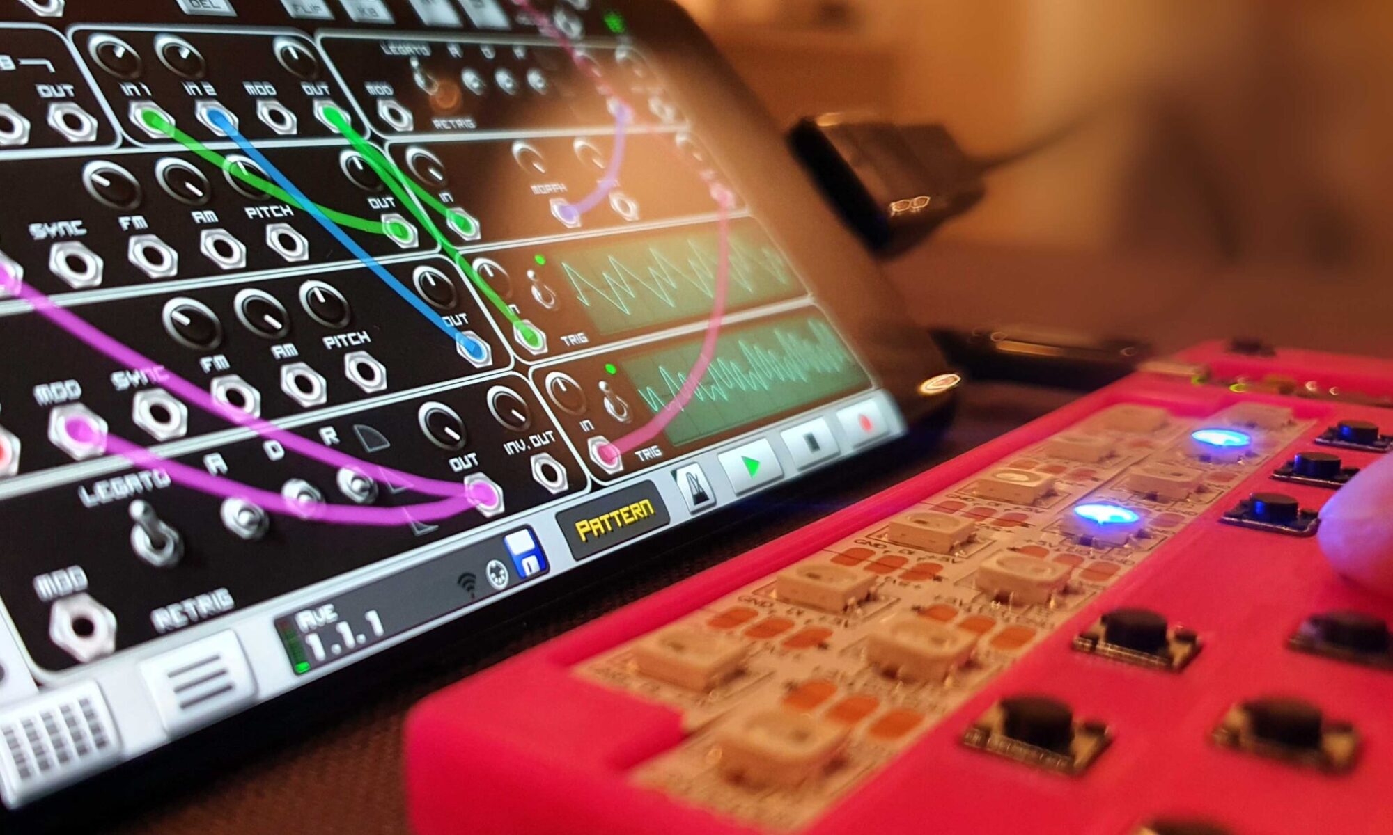
Linux based sound synthesis for LEET modules (or any other USB MIDI keyboard).

This project is suited for anyone that wants to build a powerful synthesizer engine. The project is built around the compact and affordable Raspberry Pi Zero (with WiFi) and has a miniature OLED display and six buttons. LEET Linux forms a complete synthesizer together with a USB HUB, a USB soundcard and other LEET devices (see video below).

All LEET devices use 3DPCB – a method where the circuit-board is replaced with a single 3D printed part that keeps all components in place while it also encompasses the case and structure of the product. Integrated wire channels makes it easy and fool prof to assemble and there is no need to pay and wait for a PCB delivery ;)

Demonstration of high-quality sound generation with LEET Linux running FluidSynth with Yamaha Disklavier Pro Grand Piano soundfont.

LEET Linux is part of the LEET synth project. Before continuing with the details below, it’s a good idea to read the main post first (if you haven’t already):

Part list:

  • 1x 3D printed core (3DPCB), uses 20g PLA filament.
  • 1x Raspberry Pi Zero W
  • 1x 128×64 0.96” SPI OLED display (I used the 6 pin version without CS, blue display)
  • 6x 6x6mm 4pin through hole tact switches – preferably with low activation force (50g / 0.5N)
  • 1x USB hub with micro USB cable, or a micro USB OTG adapter
  • 0.3mm copper wires (can be found in RK mains wire or similar)

Equipment:

  • 3D printer (FFF/FDM with PLA filament)
  • Solder station with a narrow tip
  • Basic tools: needle- and cutting pliers, knife, hot-glue

Build it

Print the core using a fff/fdm 3D printer. I used the following settings:

  • 3D printer: Prusa i3 MK3S with 0.4mm nozzle
  • Material: PLA
  • Nozzle temperature: 210deg C
  • Layer height: 0.2mm
  • Infill: 20%
  • Support: None

    The printing time is ~2.5 hours with default speed.

I have not made a step by step building instruction, but if you have built another LEET device, it should be sufficient to look at the illustration below.

Sound Engines

There are lots of different sound engines in Linux. So far, I have tried two different programs (FluidSynth and SamplerBox).

I hope that with the help of other LEET users the installation can be improved (providing ISO images) and more supported engines can be added. It would be nice to have ZynAddSubFX, sunvox and maybe an adaptation of zynthian in the future.

FluidSynth

I have successfully used FluidSynth (without a custom OLED interface). In the video above I used the Yamaha Disklavier Pro Grand Piano soundfont to demonstrate the quality of the sound. LEET sequencer is sending MIDI data to LEET Linux that is rendering the sound using an external USB soundcard and forwarding the MIDI events to the LEET keyboards (using aconnect command). By using pyFluidSynth, an interface can be developed in python that uses the OLED and the buttons to select soundfonts, map instruments and midi channels (3×2 buttons).

Installation of fluidsynth is quite straight forward. Follow the raspberry pi initialization below and type:

sudo apt-get install fluidsynth

Here is the bash script I used to start fluidSynth and map a LEET Keyboard to fluid MIDI:

(sleep 5; aconnect 16:0 128:0)&fluidsynth -a alsa -o audio.alsa.device='hw:1' -C0 -R0 -r48000 ./YDP-Grand.sf2

As you can see, I use plain alsa for sound generation (avoiding jack or pulseaudio that can cause additional delay.)

It is sometimes helpful to test audio to rule out other error sources:

First use this command to find the id of the attached soundcard

cat /proc/asound/modules
speaker-test -c2 -twav -Dhw:1,0  (where 1 is the id I got from the first command)

If you encounter problems, visit the forum to see if someone has found a solution to your problem, if not this is a great place to ask for assistance.

SamplerBox

I have also worked with SamplerBox and adjusted the script to use the OLED and keys to select sampleset. However, I have only got a few samples set to work properly, and haven’t figured out if the others are not working due to memory restrictions, configuration error or something else…

I hope that with the help of other LEET users the supported engines can be improved and expanded. It would be nice to add ZynAddSubFX, sunvox and maybe even adapt zynthian in the future. It would also be nice to provide ISO images for easy installations. Until then this project requires manual configuration and installation of different programs so Linux experience is preferred. But even a novice user should be able to follow the installation procedure of SamplerBox, however – expect to spend time googling for installation and configuration errors…

It was a bit tricky to use Samplerbox with the OLED display since samplerbox is using python2 while the luma library is using python3.

Here is a list of the installation steps I did:

Initialize the raspberry pi

  • Download “Raspberry Pi Imager” from https://www.raspberrypi.org/software/
  • Run and install “Raspberry Pi OS Lite” on empty micro SD card
  • Connect QWERTY keyboard, a MIDI keyboard and usb soundcard to a USB hub, connect the hub to the pi (use a micro USB OTG adapter). Insert micro SD card, Connect a HDMI display and power up the Pi.
  • Logon as default user: pi and password: raspberry
  • type:
sudo raspi-config

and change the following configurations:

  • system options/Wireless LAN (input wifi credentials to the same network as your PC)
    • system options/change password (you don’t want your raspi to become an attack vector to your network)
    • system options/Boot Autologin (select console autologin)
    • interface options/ssh (enable)
    • interface options/spi (enable)
  • unplug the HDMI cable and rebot when exit: (SamplerBox USB audio won’t work if HDMI is connected).
  • it is a good idea to configure your router and give the raspberry pi a static IP.
  • open a terminal and ssh pi@192.168.xxx.xxx (use the static IP). This enables you to cut and paste the long commands below, making installation easier.

Install SamplerBox

The following commands are copied from the merge request regarding Python3 installation of SamplerBox:

Install the required dependencies (Python-related packages and audio libraries):

  sudo apt-get update ; sudo apt-get -y install git python3-dev python3-pip python3-numpy cython3 python3-smbus portaudio19-dev libportaudio2 libffi-dev
  sudo pip3 install rtmidi-python pyaudio cffi sounddevice

Download SamplerBox and build it with:

  git clone https://github.com/josephernest/SamplerBox.git
  cd SamplerBox ; sudo python3 setup.py build_ext --inplace

Install libraries for the OLED display:

  sudo -H pip3 install --upgrade luma.oled
  sudo apt-get install libopenjp2-7
  sudo apt install libtiff5

Add LEET files

use SFTP to copy logo_128x64.png, Linux128x64, pixelmix.ttf, oledTest.py and samplerbox.py to /home/pi/SamplerBox/

Edit sound configuration

  sudo nano /usr/share/alsa/alsa.conf

change defaults.ctl.card 0 to defaults.ctl.card 1

change  defaults.pcm.card 1 to defaults.pcm.card 1

sudo /etc/init.d/alsa-utils stop ; sudo /etc/init.d/alsa-utils restart ; sudo /etc/init.d/alsa-utils start

Test Samplerbox

python3 samplerbox.py

Autostart SamplerBox:

If everything works, you can make SamplerBox autostart by changing this script:

sudo nano /home/pi/.bashrc

add this at the end:

  python3 /home/pi/SamplerBox/samplerbox.py

Download project files

All files required for this project are available at this GitHub repository:
https://github.com/vonkonow/LEET-Synthesizer/tree/main/Linux

License

This project is open source under MIT License
(Attribution is optional, but appreciated /Johan von Konow ;)

3DPCB Wi-Fi Ducky

Inject keystrokes, set up a reverse shell, or install a payload to dump passwords, all from a distance.

This is a 3D printed Wi-Fi version of the well-known USB Rubber Ducky hacking device (featured in Mr Robot). It is a very powerful PEN test tool that bypasses common security protections since it is planted inside the network (requires some social engineering). I want to raise the awareness of this attack vector and encourage anyone to build it, test it and use it for good to improve security (white hat hacking).

30 seconds demonstration

This implementation uses a 3D printed circuit board that provides the following benefits:

  • Quick and easy to build. (takes minutes to assemble)
  • Using standard components that can be found at your local supplier. (or in your drawer)
  • low cost (< $9) allows you to install several expendable units. (spray and pray) 
  • No need to wait for PCB delivery.
  • Integrates the structure of the device.
  • Compact since it stacks components in 3D. (44x30x11mm)

Credits to Darren Kitchen @ HAK5 for the original USB Rubber Ducky, and Stefan Kremser/ Spacehuhn for the WiFi version used in this build: “This is a tool. It’s neither good nor bad.
Use it to do good, to study, and to test. Never use it to do harm or create damage!”

Part list:

  • WeMosD1 mini, or clone (ESP8266 – without pin header). ~$3 on ebay
  • Arduino pro micro 5V, or clone (ATmega32u4 – without pin header). ~$5 on ebay, $4 on Alibaba
  • 3D printed circuit board (7g PLA)
  • Micro USB sync cable (not charge cable) ~$1 on ebay
  • Strands of copper wire 0.3mm

Equipment:

  • 3D printer (FFF/FDM with PLA filament)
  • Solder station with a narrow tip
  • Basic tools: Needle- and cutting pliers, knife
  • Computer to run Arduino IDE and upload firmware (using a Micro USB cable)

Design:

I wanted to test the Wi-Fi ducky and realised that I had all the parts needed at home . To keep it compact – I stacked the PCBs on top of each other and created a 3DPCB to separate and guide the connecting wires. The optional WS2812 LED was removed to keep the design as simple as possible.

Cross section of the device

I extended the unit in length to allow most part of the Wi-Fi antenna to operate freely instead of being dampened by the ground plane of the pro micro (This is the reason why the micro USB port of the WeMosD1 is not near the edge). First version worked great and this became one of those hacks where documentation took longer than the build ;)

Build it:

Here is a step by step building instruction if you want to replicate the build

Rendering showing both sides of the 3DPCB and microcontroller boards (duck yellow ;)

1. Print the 3DPCB

Print the core using a fff/fdm 3D printer. I used the following settings:

  • 3D printer: I used Prusa i3 MK3S with 0.4mm nozzle
  • Material: PLA
  • Nozzle temperature: 210deg C
  • Layer height: 0.2mm
  • Infill: 20%
  • Support: Yes

The printing time is just below one hour. While printing you can program the boards:

2. Program the two boards

  • Download the Arduino code from: https://github.com/spacehuhn/wifi_ducky. You can also find a more detailed installation instruction there.
  • Connect the Arduino pro micro, select board, port, compile and upload the corresponding firmware.
  • Connect the WeMosD1, select board, port, compile and upload the corresponding firmware. Install possible missing libraries (I needed to install SimpleCLI)

3. Assemble the Ducky

  • Remove 3Dprinted supports.
  • Thread four wires through their channels. Start from the smaller pro micro. Each wire goes through three holes. Add some tension to ensure they are tightly routed and don’t protrude any surfaces.
  • Thread four wires through the pro micro, put it in place and solder the wires from the backside of the Arduino board. Cut protruding wires.
  • Thread four wires through the WeMosD1, add some tension and solder it in place. Cut protruding wires.

4. Inspect

  • Verify the build, ensure that the boards are firmly secured and that all solder joints look proper. Rework if anything looks funny.

5. Hack

  • Connect the cable to the smaller pro micro board and connect it to your computer.
  • Connect to the wifiduck WiFi network (password: wifiduck )
  • Open a browser and visit http://wifi.duck or IP: 192.168.4.1
  • Change SSID and password (optional, but recommended).
  • Test this script to run hello world (on windows computers):

DEFAULTDELAY 200
ALT F2
GUI SPACE
GUI r
LEFT DELETE
DELAY 100 
STRING www.vonkonow.com 
ENTER

Visit Spacehuhn for detailed command descriptions and examples.

Note that microcontroller pads are exposed – do not place it on a conductive metal surface (since it might short circuit the device). Once tested you can wrap it with tape, heat shrink tubing or simply put it in the ESD bag that came with one of the microcontrollers.

Needless to say: This is an ethical hacking tool – I strongly disapprove of illegal activity and claim no responsibility nor liability for any use of this device.

Download project files

3D models for this project are available at this GitHub repository: https://github.com/vonkonow/3DPCB-Wi-Fi-Ducky

License

This project is open source under MIT License
(Attribution is optional, but appreciated /Johan von Konow ;)

LEET Control8

The Control8 MIDI unit is part of the LEET Synthesizer project. If you haven’t – It is a good idea to read the main post first before continuing with the details below:

This post describes how the Control8 unit works and what you need to build your own.

Description of the Control8 unit

Product guide. Click here to download high-resolution PDF.

Part list:

  • 1x 3D printed core 3DPCB
  • 8x 3D printed potentiometer knobs (use the version with 0 deg arrow)
  • 1x Arduino pro micro, or compatible clone (5V version. ATmega32U4)
  • WS2812 LED-strip with 8 LEDs (60 LEDs/m. I used IP60, white FPC)
  • 8x 100k trim-potentiometers (10k-500k will work)
  • 1x 25cm RK wire (containing 24 strands of 0.3mm copper wires)

Equipment:

  • 3D printer (FFF/FDM with PLA filament)
  • Solder station with a narrow tip
  • Basic tools: Needle- and cutting pliers, knife, hot-glue
  • Computer to run Arduino IDE and upload firmware (using a Micro USB cable)

Development

The Control8 is the successor to LEET Control.

Control8 has 8 analog inputs and uses the same low-cost trim-potentiometers as LEET Chord and Sequencer. In order to simplify routing, the trim-pots are rotated 90 deg compared to the other devices – so make sure to use the right 3D printed top if you want the arrow to face upward in mid position.
I recorded the process when I designed the 3DPCB for the device if anyone is interested:

Designing a 3DPCB in 10x speed (still boring unless you want to learn how it is done ;)

Build it

I have not made a step by step building instruction, but if you have built another device, it should be sufficient to look at the illustration below. The build process is very similar to the step-by-step instruction for the keyboard.

Backside view showing routing of wires.

Don’t forget to share your build in the forum. The forum is also the best place to share ideas, assist with development and  get support and help other LEET builders

Download project files

All files required for this project are available at this GitHub repository:

License

This project is open source under MIT License
(Attribution is optional, but appreciated /Johan von Konow ;)

LEET Control

The Control MIDI unit is part of the LEET Synthesizer project. If you haven’t – It is a good idea to read the main post first before continuing with the details below:

This post describes how the control unit works and what you need to build your own.

Description of the Control unit

Product guide. Click here to download high-resolution PDF.

Part list:

Component cost is around $6 on eBay October 2020 (will depend on shipping and supplier).

  • 1x 3D printed core 3DPCB
  • 4x 3D printed potentiometer knobs
  • 1x Arduino pro micro, or compatible clone (5V version. ATmega32U4) – (~$4)
  • 7x 6x6mm 4pin through hole tact switches – preferably with low activation force (50g / 0.5N) – ($0.2)
  • WS2812 LED-strip with 4 LEDs (60 LEDs/m. I used IP60, white FPC) – ($1.1)
  • 4x 100kohm High-end potentiometer with short shaft (called RK09K, RK09D, RV09 or PTV09A etc. 10k-500kohm will also work)
  • 1x 25cm RK wire (containing 24 strands of 0.3mm copper wires) – ($0.1)

Equipment:

  • 3D printer (FFF/FDM with PLA filament)
  • Solder station with a narrow tip
  • Basic tools: Needle- and cutting pliers, knife, hot-glue
  • Computer to run Arduino IDE and upload firmware (using a Micro USB cable)

Build it

I have not made a step by step building instruction, but if you have built the other devices it should be sufficient to look at the illustration below. The build process is very similar to the step by step instruction for the keyboard.

This model was made a while ago and is not using my latest 3D methods; LED-strip is soldered in place and switches can be a bit difficult to insert.

Please note that the VCC wire (magenta) routing is changing side under the LED-strip (dotted line below). Route the wire first, then LED-strip.

Backside view showing routing of wires.

Future versions

I developed this unit to test both control and arpeggiator functions. If you would like to control more than four variables, take a look at these two concept sketches. The smaller version has eight knobs and is more compact. The full size has seven knobs, and room for a label that describes the function of each knob.

Let me know which version you prefer!

Download project files

All files required for this project are available at this GitHub repository:

https://github.com/vonkonow/LEET-Synthesizer/tree/main/Control

License

This project is open source under MIT License
(Attribution is optional, but appreciated /Johan von Konow ;)

LEET Pad

The Pad MIDI keyboard is part of the LEET Synthesizer project. If you haven’t – It is a good idea to read the main post first before continuing with the details below:

This post describes how the pad keyboard works and what you need to build your own.

Description of the Pad

Product guide. Click here to download high-resolution PDF.

Part list:

Component cost is around $6 on eBay October 2020 (will depend on shipping and supplier).

  • 1x 3D printed core 3DPCB
  • 1x Arduino pro micro, or compatible clone (5V version. ATmega32U4) – (~$4)
  • 11x 6x6mm 4pin through hole tact switches – preferably with low activation force (50g / 0.5N) – ($0.2)
  • WS2812 LED-strip with 8 LEDs (60 LEDs/m. I used IP60, white FPC) – ($1.1)
  • 1x 25cm RK wire (containing 24 strands of 0.3mm copper wires) – ($0.1)

Equipment:

  • 3D printer (FFF/FDM with PLA filament)
  • Solder station with a narrow tip
  • Basic tools: needle- and cutting pliers, knife, hot-glue
  • Computer to run Arduino IDE and upload firmware (using a Micro USB cable)

Build it

I have not made a step by step building instruction, but check out the video and illustration below. The build process is very similar to the step by step instruction for the keyboard.

Backside view showing routing of wires.

Development

The pad is literally a smaller version of the LEET keyboard. I rearranged the LEDs and switches, downsized it, rebuilt the 3D model and adjusted the code.

Download project files

All files required for this project are available at this GitHub repository:

https://github.com/vonkonow/LEET-Synthesizer/tree/main/Pad

License

This project is open source under MIT License
(Attribution is optional, but appreciated /Johan von Konow ;)

LEET Chord

The chord MIDI keyboard is one of the devices in the LEET Synthesizer project. If you haven’t – It is a good idea to read the main post first before continuing with the details below:

This post describes how the chord keyboard works and what you need to build your own.

Description of the Chord keyboard

Product guide. Click here to download high-resolution PDF.

Part list:

Component cost is around $6 on eBay October 2020 (will depend on shipping and supplier).

  • 1x 3D printed core 3DPCB. Uses 34g PLA filament ($0.7).
  • 1x 3D printed knob for the trimpot.
  • 1x Arduino pro micro, or compatible clone (5v version. ATmega32U4) – (~$4)
  • 14x 6x6mm 4pin through hole tact switches – preferably with low activation force (50g / 0.5N) – ($0.2)
  • WS2812 LED-strip with 12 LEDs (60 LEDs/m. I used IP60, white FPC) – ($1.1)
  • 1x trimpotentiometer 100k (10k-500k will work)
  • 1x 25cm RK wire (containing 24 strands of 0.3mm copper wires) – ($0.1)

Equipment:

  • 3D printer (FFF/FDM with PLA filament)
  • Solder station with a narrow tip.
  • Basic tools: needle- and cutting pliers, knife, hot-glue
  • Computer to run Arduino IDE and upload firmware (using a Micro USB cable)

Build it

I have not made a step by step building instruction, but the build process is very similar to the keyboard.

Backside view showing routing of wires.

Note the addition of a potentiometer that controls the chord length. It is an ordinary low cost trimpot with a 3D printed knob glued to the top. I used a sharpie to highlight the arrow on the knob and then wiped off the top surface with an alcohol wet tissue.

Development

I wanted to see if I could create a keyboard without disharmonic sounds (no wrong keys ;). I sketched on a keyboard that played chords in different scales, tonics, root and chord length. It was a good learning experience of musical theory and after a few iterations I think I found a user interface that is easy to understand and use (despite the lack of 12 keys to select tonic note).

Embedded code for the Arduino pro-micro.

The code originates from the LEET keyboard, but with the addition of user interface for chord configuration (the upper row of keys and LEDs), and the chord generation. The ‘minor’ array is defining distance between different notes in naural minor scale. Offset the array to get different tonics. By adding an offset of two you get the major scale instead.

Download project files

All files required for this project are available at this GitHub repository:

https://github.com/vonkonow/LEET-Synthesizer/tree/main/Chord

License

This project is open source under MIT License
(Attribution is optional, but appreciated /Johan von Konow ;)